Continue to Site

Eng-Tips is the largest engineering community on the Internet

Intelligent Work Forums for Engineering Professionals

  • Congratulations KootK on being selected by the Eng-Tips community for having the most helpful posts in the forums last week. Way to Go!

Temperature Force Single Span

Status
Not open for further replies.

Son of a Bridge

Structural
May 12, 2019
18
Hello guys,

I am trying to calculate the temperature force for an abutment supporting steel girders (single span bridge). Elastomeric bearings (expansion) will be used at Abut 1. Fixed bearings will be used at Abut 2.

Questions:
How is the temperature force calculated at Abut 2 since the girders are restrained? Is the contributing length equal to the entire span length?

Initially i calculated the temperature force by calculating the superstructure displacement multiplied by the abutment stiffness. However, the force is extremely large and overly conservative when the contributing length is equal to the span length. I was wondering if the max temperature force resisted by the fixed bearing is equal to the friction force on the expansion brg before slipping occurs?

Any feedback is appreciated.

Thanks,
 
Replies continue below

Recommended for you

The forces on the 2 abutments are equal. That force is the force required to deform the elastomeric bearings the thermal expansion or contraction movement of the full superstructure length.

It's not often we have to consider that. Nearly all of our single span steel girder bridges have fully integral abutments.
 
Could you please explain why the forces would be equal if each abutment has a different stiffness (one abutment considers the elastomeric brg pad stiffness while the other ignores it)?

I guess my confusion comes from the two scenarios. Not sure which assumption is valid:

1. To maintain equilibrium, wouldnt the fixed brg be required fo resist the entire temperature load since its not displacing at all?

2. Or does the fixed brg only provide lateral resistance until the elastomeric brg pad "deforms"?

Why is the elastomeric brg "deformation" the limitation instead of the brg pad "slipping" (when temperature force exceeds friction force)?

Sorry for all the questions. Just really trying to understand the concept.

Thanks,
 
Son of a Bridge said:
...please explain why the forces would be equal if each abutment has a different stiffness...

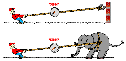
Physics, Newton's Third Law of Motion:

Newton_s_Third_Law_t2rxzi.gif
 
SRE beat me to it.

It's a single span bridge, so the abutments alone provide equilibrium. In your case, when the superstructure expands or contracts, it moves and reaches a new center point, based on the overall stiffness of the restraint at each abutment. Typically, where there are elastomeric (or any other type of expansion bearing) we assume the abutments are fixed (infinitely stiff and unmovable). This is slightly conservative, because nothing is infinitely stiff, but the relatively low shear stiffness of the expansion bearing makes it a reasonable assumption. Under that assumption, if a temperature change produces a 2" length change in the superstructure, there will be 2" of movement at Abut 1, 1" at the center of the span, and zero movement at Abut 2.

 
Wouldn’t the movement of the expansion bearing cause there to be relatively close to zero force in the abutments since the beam is not fully restrained. The thermal expansion would just elongate unrestricted in both axis.
 
jhnblgr said:
Wouldn’t the movement of the expansion bearing cause there to be relatively close to zero force in the abutments since the beam is not fully restrained.

The longitudinal force at the abutments would be equal to the force required to deform the elastomeric bearing pad at Abutment 1 (or for it to slip, if it has a PTFE sliding surface). It's typically low relative to the force required to move the abutments, and miniscule compared to the massive force that would be necessary to restrain the superstructure expansion/contraction. Granted, the force to deform the pad in shear is generally easily accommodated at abutments with deep foundations, but could cause movement of an abutment on a spread footing. I wouldn't consider it "close to zero", though.
 
Let's not kid ourselves on the stiffness of steel pile supported abutments, they are still fairly flexible, even with battered piles. Even conventional, non-integral abutments get shoved around quite a bit due to thermal forces, which is why I prefer integral abutments. Just let it move how it wants to.
 
I'll have to disagree, OSUCivlEng. Abutments with battered piles resist much larger forces than those imposed by an elastomeric pad (usually soil pressures) with very little movement. Integral abutments on H-piles are the preferred option for us, as well. Integral or not, an abutment on a single row of steel piles can, and most likely will, move, at least some. Quantifying the stiffness of the piles embedded in soil is difficult to do with a sufficient degree of accuracy to use it to reduce the required deformation capacity of the bearing pads, so we ignore it when sizing the bearing pads for a semi-integral or non-integral abutment.
 
Thank you guys for helping out.

It makes sense that the brg pad will deform before the brg pad slips. yes i agree BridgeSmith. The longitudinal force is the force required to deform the brg pad.

On another note, assume both ends of the girder are laterally restrained by a fixed connection. Do engineers typically assume the abutments will displace half of the total superstructure displacement due to thermal expansion?

 
If the abutment restraint conditions are similar, it's assumed the abutments displace equally. That typically means fully integral abutments, in which case it's of little consequence whether the movement is balanced. We have begun taking it one step further and attaching the approach slabs to the fully integral abutment and moving the expansion joint to the end of the approach slab where a sleeper slab supports the end of the approach slab and a place for the expansion joint.
 
What if the integral abutments are assumed to be infinitely rigid where they are restrained from any movement?

The axial force resisted by the girder would be extremely large.

Each abutment would resist this load? Or would the girder essentially buckle if not designed for?


Integral abutments will either move or they'll break. The forces needed to restrain the girders from axial deformation are huge, in the thousands of kips, and the buckling load is likewise huge. Integral abutments are supported on flexible foundations, most often steel H-piles. I've done one with the cap supported on concrete columns on a strip footing where the columns were hinged at the bottom of the cap.

Where we have very shallow bedrock, we typically use a semi-integral abutment, with a concrete end diaphragm encasing the girders, supported on an elastomeric pad on a stationary cap. Most often for those, we restrain the top and bottom of the pad and allow both ends to be expansion bearings.
 
BridgeSmith have you went out and looked at very many steel pile supported abutments with battered piles? They get pushed around by thermal and earth pressure forces, the type of bearings don't seem to matter. However, I'm not speaking of thermal forces from the superstructure, I'm talking about thermal forces from the pavement, especially concrete pavement.

Yes, an integral abutment supported by a single row of piles will move, because it has too. If fact it's supposed to move for the bridge to function properly.

Battered piles are a bit overrated, but they make us feel good so we use them.
 
BridgeSmith have you went out and looked at very many steel pile supported abutments with battered piles?

Not alot, but a few.

However, I'm not speaking of thermal forces from the superstructure, I'm talking about thermal forces from the pavement, especially concrete pavement.

Well yeah, the forces from expansion of concrete pavement are huge, just like the forces from expansion of a bridge superstructure. Those forces are easily 100 times the forces that elastomeric bearing pad would exert, and 10 to 20 times the typical soil pressures on an abutment. I thought you were talking about abutments with a row of vertical piles and a row of battered piles moving due to lateral soil pressure. If that happens, someone didn't do their design correctly. Our piles are typically driven to refusal, so they don't move under soil pressures. We provide adequate expansion joints to accommodate expansion of the adjacent concrete pavement. If yours don't, somebody screwed up.

 
Status
Not open for further replies.

Part and Inventory Search

Sponsor