NickParker
Electrical
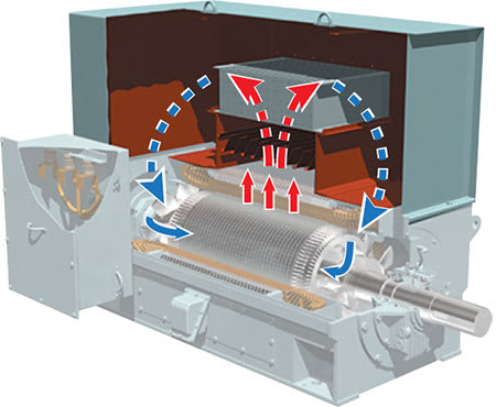
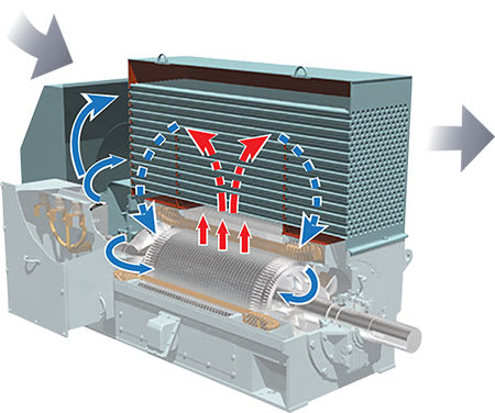
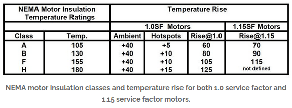
I understand the concept of temperature rise in windings, but I’m unsure about the temperature rise in a generator’s cooling system. There are two key temperatures involved: the cooling fluid’s inlet and outlet temperatures. The difference between them is the temperature rise of the coolant.
My understanding is that if this temperature difference is large, it means the cooling effect is higher, and if the temperature difference is small, the cooling is less effective.
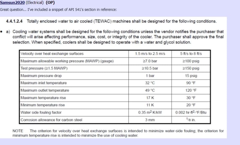
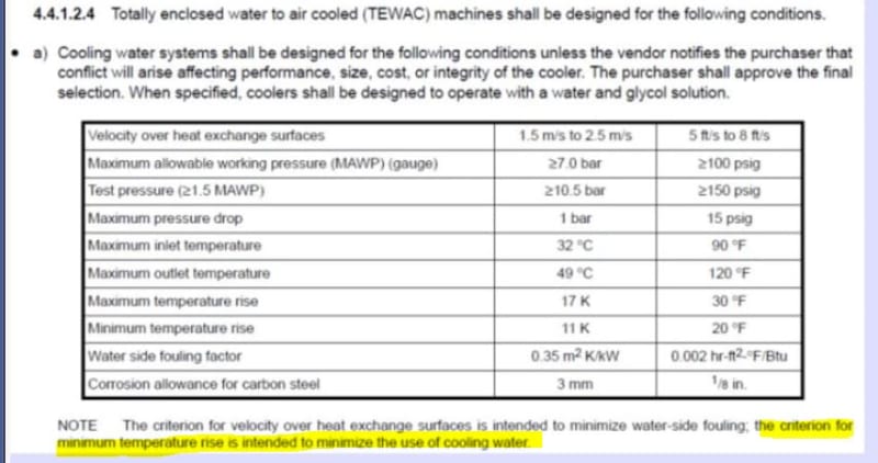
The specification states that a minimum temperature rise of 10K is required for the cooling fluid, but the vendor's datasheet shows a coolant temperature rise of 15K. Based on this, the 15K provided by the vendor should be better than the 10K specified, Is my understanding correct?
Additionally, I’ve noticed some motor specifications that limit the cooling water outlet temperature to a value like 37°C, and also restrict the coolant temperature rise to a certain level, like 7K.
Why do the specs limit the cooling water outlet temperature, and why do they restrict the temperature rise to specific values like 7K?
My understanding is that if this temperature difference is large, it means the cooling effect is higher, and if the temperature difference is small, the cooling is less effective.
The specification states that a minimum temperature rise of 10K is required for the cooling fluid, but the vendor's datasheet shows a coolant temperature rise of 15K. Based on this, the 15K provided by the vendor should be better than the 10K specified, Is my understanding correct?
Additionally, I’ve noticed some motor specifications that limit the cooling water outlet temperature to a value like 37°C, and also restrict the coolant temperature rise to a certain level, like 7K.
Why do the specs limit the cooling water outlet temperature, and why do they restrict the temperature rise to specific values like 7K?