Aytacoglu
Civil/Environmental
- Dec 4, 2023
- 40
Hi All,
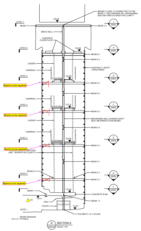
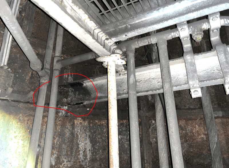
I am currently working on a steelwork repairs project for a cable shaft. The idea is to cut the ends of the beams where they have significant section losses and splice a new section in where it is going to be cut. I have attached a drawing and a photograph below just to give some idea on the works that will be undertaken and the condition of the beams.
This cable shaft consists of 7no. levels and these works are required to be carried out for each beam. Now, because height between each level is above 2.5m, there needs to be a temporary platform built in the shaft so that the workers can reach the beams and work with them.
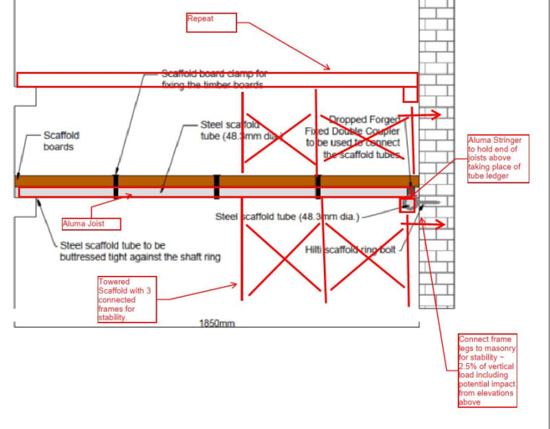
Our idea was to install eyebolt/ringbolt anchors to the masonry wall in between which is 140mm thick blockwork, and clamp the scaffold tubes to it so that the scaffold boards can be laid over. The tubes will hence be connected on one side to the wall via anchors, and it will be buttressed tight to the tunnel lining which is 100mm wide. I have attached the proposal for the scaffold arrangement below.
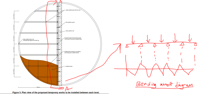
I now want to calculate which anchors I need and at what spacing does the scaffold tubes need to be for it to work. My question here is whether these bolts will experience bending moment due to the way the arrangement is for the platform. The load path will start from the timber scaffold bolts and then will be transferred to the longitudinal scaffold tubes. This load then will be transferred to the scaffold tube that will be installed parallel to the masonry wall. Due to this and the arrangement of the anchors, this will act like a continuous beam with the supports being the anchors and the point loads coming from the scaffold tubes connected via a coupler.
This will create a hogging moment at the locations of the anchors. Due to anchors being very weak in bending, although the loads here are not significant, the anchors are struggling to pass the design checks.
Could anyone please confirm/agree with the method of analysis I am using here? That the load path will be as described and the bending moment created due to the arrangement?
I would really appreciate if anyone can assist.
Thanks!


I am currently working on a steelwork repairs project for a cable shaft. The idea is to cut the ends of the beams where they have significant section losses and splice a new section in where it is going to be cut. I have attached a drawing and a photograph below just to give some idea on the works that will be undertaken and the condition of the beams.
This cable shaft consists of 7no. levels and these works are required to be carried out for each beam. Now, because height between each level is above 2.5m, there needs to be a temporary platform built in the shaft so that the workers can reach the beams and work with them.
Our idea was to install eyebolt/ringbolt anchors to the masonry wall in between which is 140mm thick blockwork, and clamp the scaffold tubes to it so that the scaffold boards can be laid over. The tubes will hence be connected on one side to the wall via anchors, and it will be buttressed tight to the tunnel lining which is 100mm wide. I have attached the proposal for the scaffold arrangement below.
I now want to calculate which anchors I need and at what spacing does the scaffold tubes need to be for it to work. My question here is whether these bolts will experience bending moment due to the way the arrangement is for the platform. The load path will start from the timber scaffold bolts and then will be transferred to the longitudinal scaffold tubes. This load then will be transferred to the scaffold tube that will be installed parallel to the masonry wall. Due to this and the arrangement of the anchors, this will act like a continuous beam with the supports being the anchors and the point loads coming from the scaffold tubes connected via a coupler.
This will create a hogging moment at the locations of the anchors. Due to anchors being very weak in bending, although the loads here are not significant, the anchors are struggling to pass the design checks.
Could anyone please confirm/agree with the method of analysis I am using here? That the load path will be as described and the bending moment created due to the arrangement?
I would really appreciate if anyone can assist.
Thanks!