Eng-Tips is the largest engineering community on the Internet

Intelligent Work Forums for Engineering Professionals

  • Congratulations waross on being selected by the Tek-Tips community for having the most helpful posts in the forums last week. Way to Go!

Tensile Testing of 3D printed metallic coupons

Status
Not open for further replies.

HeavenSpace

Mechanical
Aug 3, 2006
3
0
0
SG
Hi,

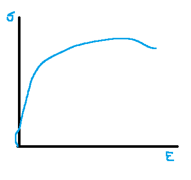
I've just completed some tensile testing of 3D Printed Aluminium coupons, and the results look suspect. Can anyone shed some light as to what could have caused the initial anomaly in the Stress-Strain diagram?
Stress_Strain_Curve_fnyppt.png


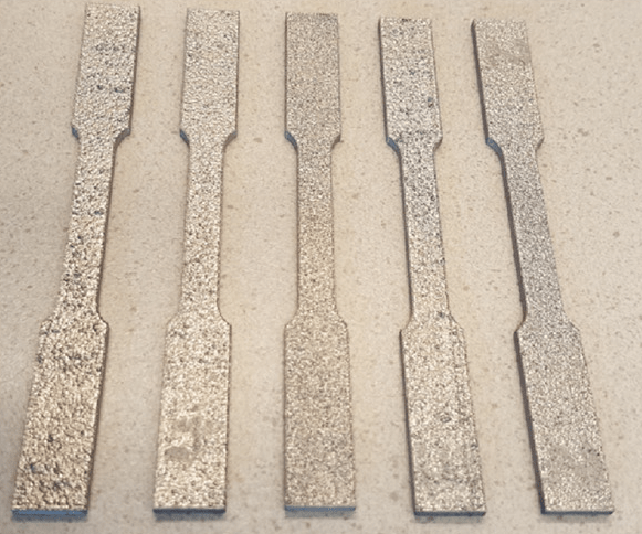
A second question I have is that I am looking to tensile test coupons in the "As-printed" condition i.e. no machining, grinding, etc. I thought the test might be meaningless, since there are so many variables involved when the samples are "as is". Any comments?
3D_coupons_mpbcig.png
 
Replies continue below

Recommended for you

What anomaly? The shifting extensometer? this is likely due to the rough surface and various amounts of porosity in the parts.

Were these all printed at once? In the same orientation?
One caution, if you print bars in various orientations they will all be different, maybe by over 50%.
Different strength, different modulus, different elongation, you get the idea.

If you are trying to make parts that will be used with no surface machining then you should test that way. If the parts will be machined then machine your bars. Machining the bars to achieve more consistent test results when your service parts will be as-printed can lead to some very bad assumptions.


= = = = = = = = = = = = = = = = = = = =
P.E. Metallurgy, Plymouth Tube
 
How are you measuring strain, and how are you measuring/calculating stress? I can imagine a contact extensometer slipping on the rough surfaces you show and possibly creating the artifact (think of one or both extensometer point(s) riding on a "peak" at the test start, but then being jostled down the "backside" of the peak when the test begins (due to machine vibrations?), giving a negative indicated displacement). But if the artifact is consistent across a number of tests, then...hmm.

I admire the idea of testing in the as-produced finish, but it will make it harder to accurately measure the dimensions. It might be instructive to test both ways; the number of variables as you noted will grow accordingly.
 
3D printing is the biggest misnomer out there.
By what process was material (presumably aluminum in some form) transmogrified into sheet form?

"Everyone is entitled to their own opinions, but they are not entitled to their own facts."
 
If the anomaly were caused by shifting extensometer (due to rough surfaces), then shouldn't this be consistent throughout the curve?

I should have clarified that the 2 pictures are not related. The coupons that that were tested have been machined as per test requirements, so there were no rough surfaces.

This statement: "If you are trying to make parts that will be used with no surface machining then you should test that way." I don't quite agree. If the test samples were not prepared properly, then wouldn't the test results be meaningless since there are now so many variables e.g. notches, varying cross-sectional areas, etc.
 
In many cases it is possible that the outer surface of such a part has very different properties from the bulk material, often either lower strength or lower ductility. If you only ever test prepared bars you can miss this and get part performance that is significantly different from the expected.

How many did you test? How many looked like this?
How is your extesometer clamped to the part?

= = = = = = = = = = = = = = = = = = = =
P.E. Metallurgy, Plymouth Tube
 
Test machines don't back up so there is some other flaw in the way the samples were measured. The sample would have to add energy to itself to reverse the curve if there was no slippage.

If it was slipping it would not be consistent. It would scrape up a chunk of material until it gouged a big enough piece to hold onto.
 
Hi EdStainless, OK, thanks for pointing out. I think the keyword I was struggling to find is "Bulk Material". So, a standard test should reveal the intrisic properties of the as-built "bulk material". 3D printed parts are expensive, so I don't think we are planning to test more than 5 samples.
 
3D printed parts are expensive
Ah, that's the part that tech geeks and hypesters never mention.

"Everyone is entitled to their own opinions, but they are not entitled to their own facts."
 
Pretty common to see such a curve when grip flips, you often push down (compress, 5-10 lbs force) specimen to have the teeth hold the it firmly. you get a reverse curve at the very beginning. The machine can normally correct itself when calculate modulus, if not, you can manually draw a straight line to skip this portion.
 
"only test five parts" because of "expense" ?????

WRONG!

You're going to make 5,000. 50,000. 500. Doesn't matter really.

You MUST KNOW the quality (degree of standardization" of your raw material (1),
and (2) you must know the effect of your machining and notching or threading or drilling or forging/bending will have on the raw stock into a final shape and final imposed new residual stresses and strains.

For the test pieces, machine the two ends (both sides) of the test section, or use a common uniform serrated vise jaw to positively clamp the rough 3D ends before pulling begins. Do not machine the center of the test portion - Your raw stock crystals and grain size tested MUST match the raw stock crystals and grain size in your final part.

(If the final stock is stamped or folded, that stamping and folding (cold forging!) will greatly affect the actual crystals actually receiving the in-use stresses. So you must test those characteristics. Yes, "test coupons" are used to prove test coupon properties, and then those properties are used to design the metal shapes in the final part. Been that way since metallurgy began in the 1810-1830's. BUT! 3D modelling breaks every one of the "assumptions" safely made by engineers since blacksmithing began. Large "globs" of metal each a separate crystal with a separate grain structure are deposited like sandstone or Styrofoam pellets next to each other. The only "forces" holding the separate balls together are the tiny surface areas where each "ball" is touching its nearest neighbor unless the deposited balls are compressed into each other. Cold forged.

Even old-fashioned castings have more uniform crystals across the entire solidified volume.
 
We were doing some work with a AM pump impeller for a development project. The dimensions were correct but the flow curves were very odd. The midrange looked OK but both high pressure and high flow ends were very distorted.
We had test pieces made at the same angle of incline as the vanes, with some in the radian direction and some in the Z.
Low and behold the modulus was different by a ration of 2:3.
Our vane angle was changing under load because the material flexed much more in one direction than the other.
The test pieces cost us more than the parts, but ti told us that we could only trust a portion of the data.
If we hadn't of done the testing we would have scraped the design because it didn't perform. And now we know the limitations of this method. And we know that we can't make real parts this way (at this time, in this material,..).

= = = = = = = = = = = = = = = = = = = =
P.E. Metallurgy, Plymouth Tube
 
Status
Not open for further replies.
Back
Top