Continue to Site

Eng-Tips is the largest engineering community on the Internet

Intelligent Work Forums for Engineering Professionals

  • Congratulations SSS148 on being selected by the Eng-Tips community for having the most helpful posts in the forums last week. Way to Go!

Tension on a Fillet Weld 1

Status
Not open for further replies.

StrEng007

Structural
Aug 22, 2014
543
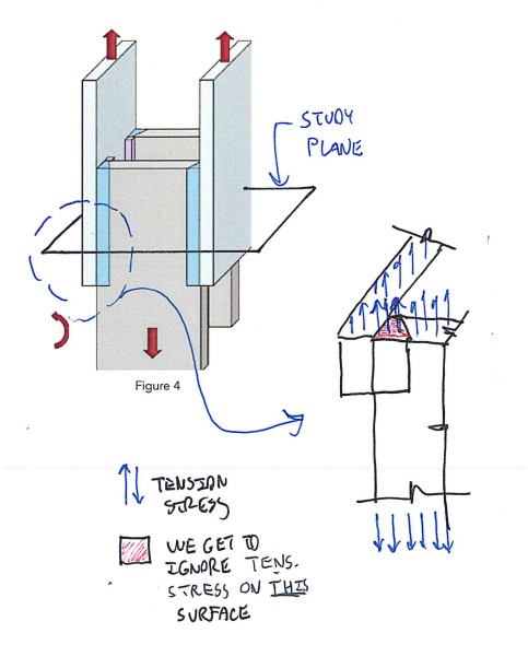
Table J2.5 of AISC 360-05, Fillet Welds Section, Tension or Compression parallel to a weld axis states: Tension or compression in parts joined parallel to a weld need not be considered in design of welds joining the parts. Graphically, what does this mean?

To simplify, let's say I have a cantilevered flat bar, 3"x1/2", long dimension vertical, with fillet welds along each 3" face. Ignore the length of the cantilever. At the end of the bar I have a vertical load acting down and a lateral tension load pulling away from the host support.

Typically, I'll resolve the vertical load into a y-component stress, y1. Next I'll find the moment induced tension on the weld and calculate the x-component stress at the furthest distance from my centroid, x1. Next I'll find the additional x-component stress from the tension load alone, x2. Resolving these forces [(y1)² + (x1+x2)²]0.5 = the resolved stress on my weld. This will be used to size the weld, etc. (For the record, as you can see, I'm using an elastic vector analysis)

At what point can I ignore the tension or compression stress as mentioned in Table J2.5? Is this ONLY when there is a tension force, and no other force that is inducing shear through the axis of the weld?
 
Replies continue below

Recommended for you

Resolving these forces [(y1)² + (x1+x2)²]^0.5
 
It is not clear to me why a force parallel to the axis of the weld can be ignored.

BA
 
I believe that the clause is saying this:

1) The welds do have to be designed for the shear demand that would arise in the welds as a result of the tension being transferred between connected parts.

2) The welds do not have to be designed for the tension demand that would arise in the welds (parallel to the weld axis) as a result of the tension being transferred between connected parts.

Weld tension does of course arise as a result of strain compatibility in all the parts of the connection, including the welds. We deem that to be of minimal significance, however.

I like to debate structural engineering theory -- a lot. If I challenge you on something, know that I'm doing so because I respect your opinion enough to either change it or adopt it.
 
KootK,
I'm a little confused about what you're saying. What about the tension demand that is a result of an eccentric shear load, placed out of plane? In your first statement, I'm picturing a tensile force being resolved through a tension member that is welded in-plane with its attachment surface. Whether this load is concentric or not, all forces result in shears due to the load being in-plane.

The second statement seems to agree with what I was questioning above. That the tension on the weld does not have to be considered when it's a pure tension load (out of plane).

With that being said, how would you accurately use the AISC table and approach the scenario where you have pure tension, pure shear, and a moment induced tension like the scenario I listed above?
 
StrEng007:
I don’t have that code section in front of me, but my take on what I think they mean, about what you are looking at is....
They do not mean that you can ignore tension and compression forces/loads (their induced stresses) on the joint or weld. They generally mean that when the forces/stresses are parallel to the axis of the weld, or acting in a plane parallel to your canti. 3x .5" bar, they will stress the weld in shear, with the min. weld area being through the weld throat. This is basically our normal approach to sizing the fillet welds, and of course, you do have to look at combined stresses or combining forces so you do look at the max. stress condition. Try reading this code section in that light and see if it makes more sense.

They are trying to worn you against load conditions which might load the weld in another less favorable/desirable way. For example, if your loadings or stresses induce tension perpendicular to the axis of the weld, particularly if it is tension across the root of the weld, this is not a good condition at all. A prying action across the root of the weld would not be good either. Alternatively, if you fab. a ‘T’ section and have fillet welds on both sides of the web, to the flg., you have a balanced weld condition and minimize or eliminate the tension or prying across the weld root, and the weld essentially takes any tension, in shear/as shear, at the throat of the two welds. This is an acceptable condition when designed correctly. If your loads pry on the weld, at its start or termination, any reentrant corner, etc, where combined stresses are particularly high , in such a way as to start to unzip the weld, this is not a good condition either, and it must be designed out of the detail.
 
StrEng007 said:
I'm a little confused about what you're saying.

Yeah. Even as I was typing my response, I was thing that a sketch would almost certainly be required. My bad for being lazy. Try the sketch below and let me know if my intent is still unclear.

StrEng007 said:
how would you accurately use the AISC table and approach the scenario where you have pure tension, pure shear, and a moment induced tension like the scenario I listed above?

Assuming the shear to be uniformly distributed along the 3" dimension, you would have none of the weld tension force being discussed here (by me at least). Consequently, some version of the instantaneous center of rotation method (like yours) would be the likely way to go.

Capture19_g37ucl.png


I like to debate structural engineering theory -- a lot. If I challenge you on something, know that I'm doing so because I respect your opinion enough to either change it or adopt it.
 
Similar to what KootK is saying...

Imagine a built up plate I-section that's acting as a column carrying 20 kips. That 20 kips would be divided by the area of the column, which would include the fillet welds, to get the stress. However, the compressive stress in the fillet welds is minimal so it can be ignored.
 
Status
Not open for further replies.

Part and Inventory Search

Sponsor