Eng-Tips is the largest engineering community on the Internet

Intelligent Work Forums for Engineering Professionals

Terminal boxes vs connectors 1

Status
Not open for further replies.

MarcT

Mechanical
Apr 3, 2018
4
0
0
NL
Hi everyone,

I am wondering about the difference between connections made in a terminal box as opposed to the connections in a dedicated connector. As a mechanical engineer this really isn't my cup of tea, but I'm trying to understand this requirements behind the two different situations to be able to make design choices.
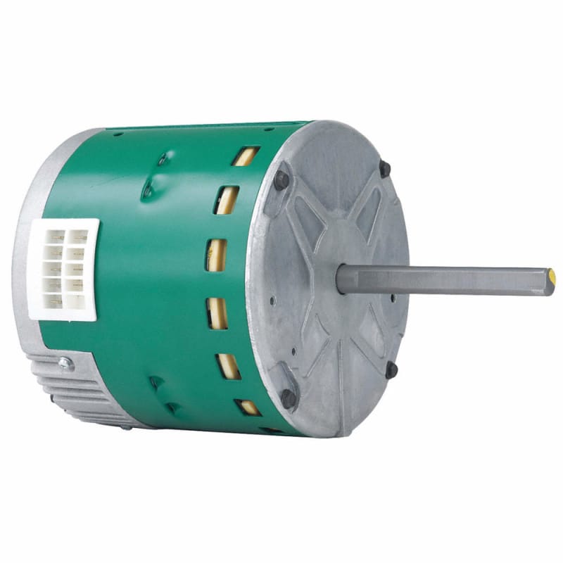
What puzzles me is that for terminal boxes like in this image both CSA and UL standards require a certain amount of air volume in the box (123 cc total or 24 cc per conductor).
delta-connection.jpg

When you use a connector such as these from TE to make the same electrical connection (same voltage/amp requirements) there is no air volume requirement.

So why is this the case? And might it be allowed to use the principles of the terminal box (screw a conductor to a terminal) while circumnavigating the air volume requirement by for example closing off the connection terminals to a similar degree as in a connector?
Before you ask why I would want this; standard connectors in the required rating are too large for our purpose, but terminal blocks aren't.

I hope someone can help me make sense of this.
Thanks!
 
Replies continue below

Recommended for you

I can't explain the air volume requirement.

I can explain why the connector option exists.
In a union shop, absent connectors, if some electrical component fails, you need to round up at least two tradesmen to replace the faulty component. E.g. millwrights are allowed to have screwdrivers, but they are not allowed to use them on electrical terminations, or even a t.b. cover. And electricians can't do rigging or lift heavy objects like motors. But a millwright is authorized to mate and demate connectors, as well as shaft couplings and mounting bolts.


Mike Halloran
Pembroke Pines, FL, USA
 
You mentioned CSA.
Under CEC:
The volume requirement is for the conductors, not the terminals.
The code rule is intended more for junction boxes to provide adequate working space.
Connectors are typically used for motors that must be changed out frequently.
A connector adds cost and another point of failure.
There are safety issues associated with connecting or disconnecting a large motor with a plug type connector when the circuit is energized.
And, unless the motor is a special build, you would install the connector on the end of a cable that is connected to the motor in the normal terminal box.
The space required varies with the size of conductor.
This rule may not apply to motor terminal boxes. Not sure.

Bill
--------------------
"Why not the best?"
Jimmy Carter
 
Thanks for your replies, gents.

So Bill, if I understand your remark
waross said:
The volume requirement is for the conductors, not the terminals.
The code rule is intended more for junction boxes to provide adequate working space.
correctly then if the cover would be a box open on one side and the terminals are "out in the open" when the cover is off the working space would be large enough. However, this doesn't help me understand why there is a volume requirement at all, whether it is for the conductors or the terminals. The conductors we are talking about are rather small, only 2.5 mm[sup]2[/sup].

We would like to avoid connectors for the exact reasons you also state: cost, possible failures and in our case also strong dimensional limitations. Our motors aren't meant to be disconnected often. If it occurs it should only be for replacement and will (should) never occur on a live circuit.


Marc
 
Is the volume requirement just an easy way to ask for enough space for all the cables that are trying to find their way to the right place to get there without too much of a fight and without getting too badly mashed when it's time to try to put the cover on.

I'm sure I'm not the only person here who's had to deal with too-fat cables that some nutter has forced into a too-small terminal box until the cable insulation chafed through, creating an unsuitable liaison between Phase and Earth.

@MarcT: (Apologies for the egg-sucking lesson here) The junction box in your photo is doing two different jobs: As well as attaching the incoming cable to the motor, it uses the six terminals and three links to let you build yourself two quite different motors. That's not an option the connectors offer.

A.
 
The connector you linked to seems to be only for very small motors like stepper motors. For normal industrial motors, I don't see that happening due to their size requirement.

zeusfaber

I am with you. I never got the logic of 'cost cutting' on terminal boxes, whose 'footprint' is negligible when compared to the motor itself. Many a client have requested and are very happy with modified bigger terminal boxes we do for their motors.


Muthu
 
Hi guys. Maybe I need to clarify a bit. I'm not talking about large size stationary industrial rotating motors. The motors I'm working on are:
[ul]
[li]Synchronous linear motors, 600VDC, up to 25A.[/li]
[li]Small (50 x 30 x 100 mm for the smallest version)[/li]
[/ul]

So this has two effects:
[ul]
[li]The terminal box would be part of the moving half of the motor. The magnet track is the stationary part.[/li]
[li]A motor with a terminal box which is larger than the motor itself is unsaleable.[/li]
[/ul]

The wires used for these small motors are max. 1.5mm[sup]2[/sup], and 2.5mm[sup]2[/sup] for the larger types (which of course could have a slightly larger terminal box). The problem is that, as far as I know, these small motors still follow the same standards thought out for the big ones, but the standards don't scale down to "our level".

@zeusfaber, no problem. I'm here to learn. I get that the work area should be ergonomical etc. I don't exactly get what you mean by the two different motors in your last comment. Are you referring to the difference between star and delta connections.
 
Found a new acronym today:
ECM, Electrically Commutated Motor. I think that this is a more descriptive name then Brushless DC motor.

Check with motor manufacturers. Here is a brushless DC motor from Grainger with a plug-in connection.
12V752_AS01_tcncqi.jpg


While this is not a brushless/Electrically Commutated Motor, it illustrates a common type of small motor with an end terminal box.
image_gqh84r.png


There are also motors available with a cable connection.
2PUX4_AS01_oty50p.jpg


For large quantities, consult the manufacturer for special features.
For small quantities, find a motor rewind shop that will modify a motor by replacing the terminal box with a cable.
Note: You don't need a connector. The cable may be run to a fixed junction box.

Bill
--------------------
"Why not the best?"
Jimmy Carter
 
Pleading ignorance on Synchronous Linear Motors, I’ve typed in the term at Google and now understand what the OP is dealing with.

From an SEW Instruction Manual:

Perform electrical installation according to the pertinent regulations (e.g. cable cross sections, fusing, protective conductor connection).
For any additional information, refer to the applicable documentation.
Comply with the regulations of the following standards and directives:

EN 60034-1, rotating electrical machines

EN 50110, operation of electrical installations

IEC 60664, insulation coordination for equipment within low-voltage systems

EN 60204-1, safety of machinery - electrical equipment of machines

EN 61800-5-1, adjustable speed electrical power drive systems
The connection must be a permanently secure electrical connection (no protruding wire ends)
use the cable end equipment intended for this purpose.
Establish a safe PE connection. When the motor is connected, the distances to non-insulated and live
parts must not be shorter than the minimum values according to IEC 60664 and national regulations.

Not that any of the above answers the OP’s question. It at least better explains why the connection to the motor is an issue.

Additionally: The designated use of SEW EURODRIVE synchronous linear motors is as components for installation in machinery and systems.
The manufacturer of the machine or system is responsible for complying with the EMC Directive 2014/30/EU

John
 
Including the first picture that the Original poster posted.
The point is that there are many motors without a large terminal box.
But your point is taken.

Bill
--------------------
"Why not the best?"
Jimmy Carter
 
The answers so far are surprising;
While I acknowledge that cramming too many wires in a box makes them harder to connect properly, I thought that the box size requirements (motor connection boxes and electrical outlet/switch boxes alike) were determined to give a sufficient space of air to prevent the conductors from mutually heating each other. The insulation temperature rating is based on heat loss in free air, which definitely isn't free inside boxes or conduits.

STF
 
Some points to ponder:
In the Canadian Electrical Code:
1 The wire space rules do not apply to terminal boxes that are part of a motor.
2. The heat generated by the conductors is ultimately dissipated by the outside surface of the box.3. The heat generated is a function of the length of the conductors and that is not addressed in the code.
3. The heat/volume ratio in a junction box will be less than the heat/volume ratio in a length of conduit.
4. Part of the heat rejection circuit of the junction box is the box walls. These may be sheet steel, die cast, cast malleable iron or some type of plastic. The code does not consider the material or thickness of the junction box material.
5. The conductor space rule does not apply to pull boxes or condulet type fittings. eg. Ts and LBs when the wire pass straight through.
6. When a splice or connection is made in a T or LB then the space rule does apply and the fitting must generally be oversized in relation to the conduit size.

Bill
--------------------
"Why not the best?"
Jimmy Carter
 
This is probably not going to be much of help, but some insight from electric (DC) subway trains - most high-voltage connections are made through connection boxes similar to these for reasons of connection reliability* and for fire safety (all nodes/connectors/points of attachment are considered to be hazards). On subway trains specifically, these boxes are made of metal or another fire-resistant material.

* Experience from operating these trains that I was researching shows that in cases of overcurrent, the points where wires are connected to the devices are most often the failure points. In some cases, inadequate tightening of the contacts caused them to burn away even during normal operations. In yet other cases, insufficiently tightened contact caused repeated heating on that one terminal, leaving traces of discoloration. On the trains I work with, ALL of high-power devices are connected this way, no connectors are used and all boxes are rated to contain possible electrical fires.

Generally, with subway train traction system, the manuals call for thorough cleaning of terminals and the wires, plus maximum permitted tightening of the bolts to ensure no 'parasitic' resistance.
 
Thanks Bill,
...meaning, heat dissipation is not as significant as other issues, then.

Black Phoenix said:
...insufficiently tightened contact...

Insufficiently tightened, or permitted to loosen by either/all of vibration, inadequate thread-locking, thermal cycling?


STF
 
That is my understanding, SparWeb. The CEC code rule applies to junction boxes, not motor terminal boxes and the intent is to provide adequate working space. Loose connections are bad no matter where they are.

Bill
--------------------
"Why not the best?"
Jimmy Carter
 
Status
Not open for further replies.
Back
Top