Davavanstone
Automotive
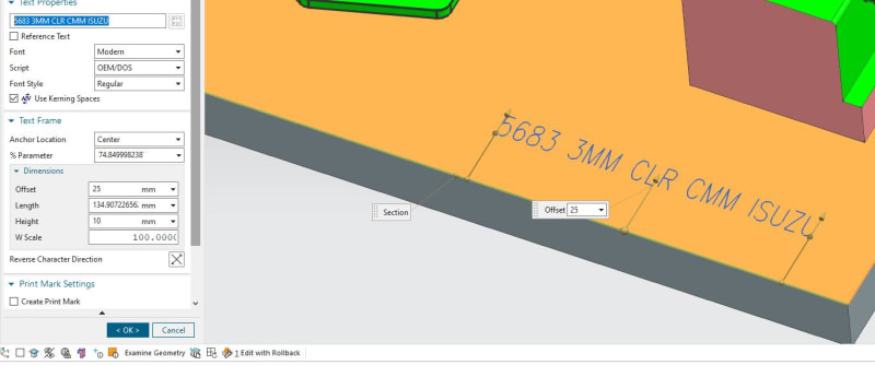
Hi, I'm using NX2212 and am having some trouble engraving text. I want to model the text for another machinist to manufacture. I don't want to simply extrude cut a font into the part, this is not machinable, corners cannot be machined, and it means a lot of toolpaths to cut the extruded face.
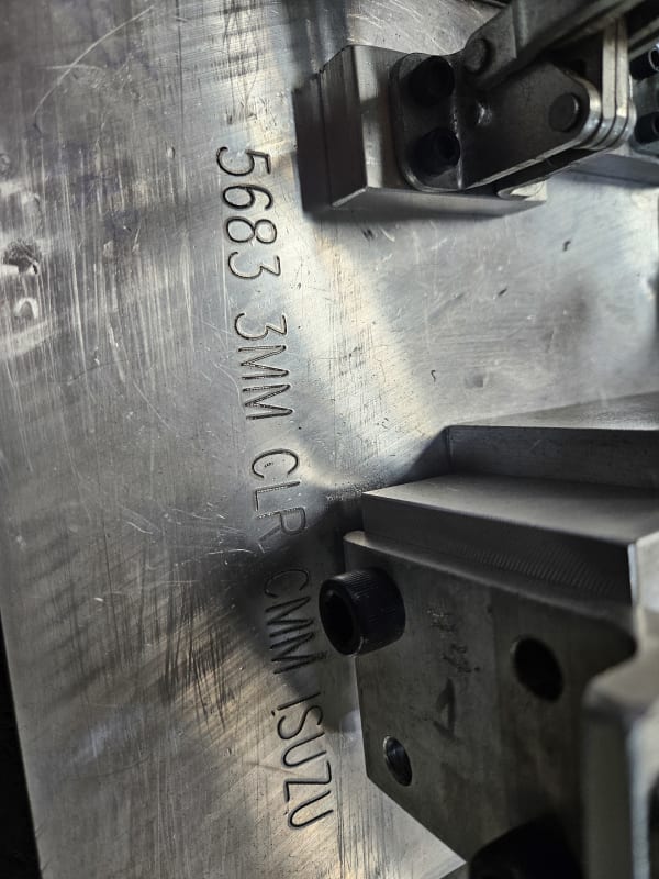
My font would need to be engraved with a 1mm ball end mill.
My current workflow, and this works for sketches, but no fonts, is to extract the surface, then offset the surface by .4 then draw a sketch on a plane at distance then project the curves to the offset surface. I would place a sphere at 1mm diameter at the corner of a curve or wherever required, then use swept volume with the sphere. This yields an "engrave" EXACTLY as it would be done when milled. If engraving on a flat surface, I skip the offset surface part and just use a sketch on a plane at .4mm away.
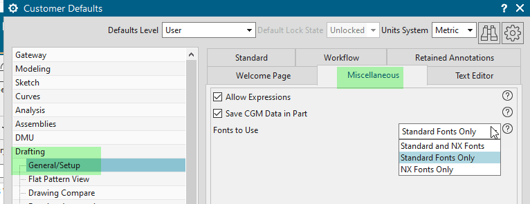
Now, the issue is fonts... I have scoured the internet for months for a TRUE single line/stroke font so I can engrave text in this way, I've found quite a few but they always fail with swept volume. The tool has very little verbosity, so I've no idea why it fails.
A work around is to put a sketch on the same plane, and "trace" the text into true geometric shapes rather than faceted curves. This works but it's very time consuming.
Do true single line TTF fonts that aren't faceted actually exist?
Is there something I'm missing on how to do this more efficiently?
My font would need to be engraved with a 1mm ball end mill.
My current workflow, and this works for sketches, but no fonts, is to extract the surface, then offset the surface by .4 then draw a sketch on a plane at distance then project the curves to the offset surface. I would place a sphere at 1mm diameter at the corner of a curve or wherever required, then use swept volume with the sphere. This yields an "engrave" EXACTLY as it would be done when milled. If engraving on a flat surface, I skip the offset surface part and just use a sketch on a plane at .4mm away.
Now, the issue is fonts... I have scoured the internet for months for a TRUE single line/stroke font so I can engrave text in this way, I've found quite a few but they always fail with swept volume. The tool has very little verbosity, so I've no idea why it fails.
A work around is to put a sketch on the same plane, and "trace" the text into true geometric shapes rather than faceted curves. This works but it's very time consuming.
Do true single line TTF fonts that aren't faceted actually exist?
Is there something I'm missing on how to do this more efficiently?