Continue to Site

Eng-Tips is the largest engineering community on the Internet

Intelligent Work Forums for Engineering Professionals

  • Congratulations KootK on being selected by the Eng-Tips community for having the most helpful posts in the forums last week. Way to Go!

The design shear strength for RECTANGULAR BARS AND ROUNDS-ANSI/AISC360-16 4

Status
Not open for further replies.

AYMAN5000

Civil/Environmental
Dec 25, 2022
18
HELLO
The design of rectangular bars and rounds under bending can be found in the manual as per section F11.
However, AISC-360-16 chapter G did not provide any equation when designing (rectangular bars and rounds) under shear !!
I have searched the manual of steel design by SAP2000 V24.1 and I found that SAP2000's manual provided equation G2-1 to solve this issue without any reference as per attached!!!!.
Kindly I need a Professional reply.
 
 https://files.engineering.com/getfile.aspx?folder=fd6737b0-f05b-4915-9170-296c2a77c3b3&file=SAP2000.jpeg
Replies continue below

Recommended for you

In the 2016 specification, rectangular bars and rounds would be covered under equation G4-1 for singly and doubly symmetric members. Looks essentially the same, just a slight reorganization.
SmartSelect_20221225-085902_Drive_lpbii5.jpg
 
For solid bars, you should probably also consider that peak shear stress is greater than the average shear stress. Although if it's a member in a sap model the proportions are probably such that shear won't be near failure anyway.
 
I think the 0.6 factor, at least for square/rectangular sections accommodates the 1.5x actual shear stress increase...

-----*****-----
So strange to see the singularity approaching while the entire planet is rapidly turning into a hellscape. -John Coates

-Dik
 
@Lomarandil
it seems that the factor CV2 has no relation to round sections (solid bar) see the following definition
For other singly or doubly symmetric shapes
Aw = area of web or webs, taken as the sum of the overall depth times the web
thickness, dtw, in.2 (mm2)

Cv2 = web shear buckling strength coefficient, as defined in Section G2.2, with
h / tw = h/ t and kv = 5
 
The following would be a conservative approach, which sounds like what SAP2000 is doing.

Limiting stress equals the shear yield stress from the von Mises yield criterion: Fy/sqrt(3), which is approximated as 0.6Fy in AISC.

Computed maximum shear stress = VQ/It.

Set the computed stress equal to the limiting stress and back out V -- that's Vn. Use a 0.9 phi factor or 1.67 Omega factor.

Check out the commentary to the Specification G5. It describes a similar method for round pipes.
 
AYMAN ABOUELAMAYN said:
@Lomarandil
it seems that the factor CV2 has no relation to round sections (solid bar) see the following definition
For other singly or doubly symmetric shapes
Aw = area of web or webs, taken as the sum of the overall depth times the web
thickness, dtw, in.2 (mm2)

Cv2 = web shear buckling strength coefficient, as defined in Section G2.2, with
h / tw = h/ t and kv = 5

Shear buckling would be impossible for a round section (or square section, or rectangle bent about its minor axis) so Cv1 or Cv2 would be 1.0.
 
271828 said:
Shear buckling would be impossible for a round section (or square section, or rectangle bent about its minor axis) so Cv1 or Cv2 would be 1.0.
Based on your latest reply, I believe that equation G4-1 is not the correct equation when designing shear for round bars.
 

Thanks... I'd always thought it was due to the parabolic distribution vs. uniform distribution.


-----*****-----
So strange to see the singularity approaching while the entire planet is rapidly turning into a hellscape. -John Coates

-Dik
 
AYMAN ABOUELAMAYM said:
Based on your latest reply, I believe that equation G4-1 is not the correct equation when designing shear for round bars.

That's correct because h and t aren't defined for a circular section.

I think there are two practical options:

The first option is to consider "failure" to be at first shear yielding at mid-depth. That's the approach I typed about above.

The second option is to compute the fully plastic shear strength with 0.6Fy over the entire cross-sectional area. With that approach, Aw would be the area of the circle. That's similar to what is done for bolts.

The first option is more conservative. If it results in a reasonable strength ratio, then I'd go with it and move on.
 
dik said:
Thanks... I'd always thought it was due to the parabolic distribution vs. uniform distribution.

That is my understanding anyway. In other codes and research I've seen, they stick with tau_y = Fy/sqrt(3) or 0.577Fy or 0.58Fy.
 
271828 said:
That's correct because h and t aren't defined for a circular section.

I am still searching for the right equation for round bars.
If I am going to use equation G2-1 (recommended by SAP2000) OR G4-1 recommended by Lomarandil
both Cv1 & Cv2 are equal to 1.0 and the two equation give the same results.
Take note that Lomarandil has a good point of view round bars are considered DOUBLY SYMMETRIC MEMBERS so equation G4-1 may be applied.
from my point of view I suggest the following equation
1_yyohla.png

its all about the strength reduction factor shall we use 0.9 as per Equation G2-1 & G4-1
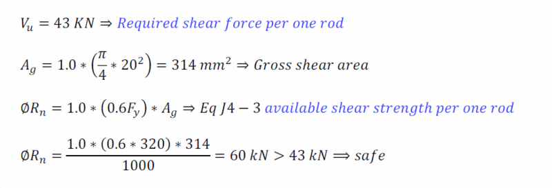
or strength reduction factor = 1.0 as per J4-3.
 
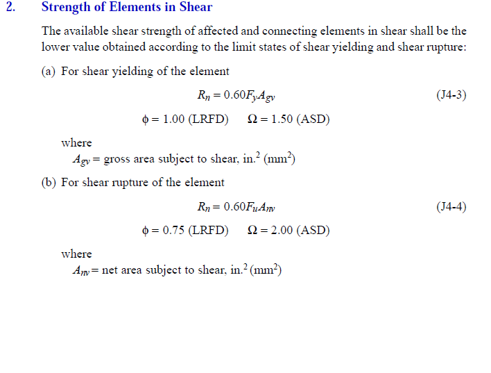
Eq. J4-3 is the second option that I mentioned yesterday, except for the phi factor.

For a connected part (Section J4) use phi = 1.00.

For a member (Chapter G) use phi = 0.9.

You'll have to judge whether your component is more like a connected part or member, and select the phi based on that.
 
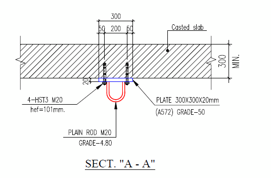
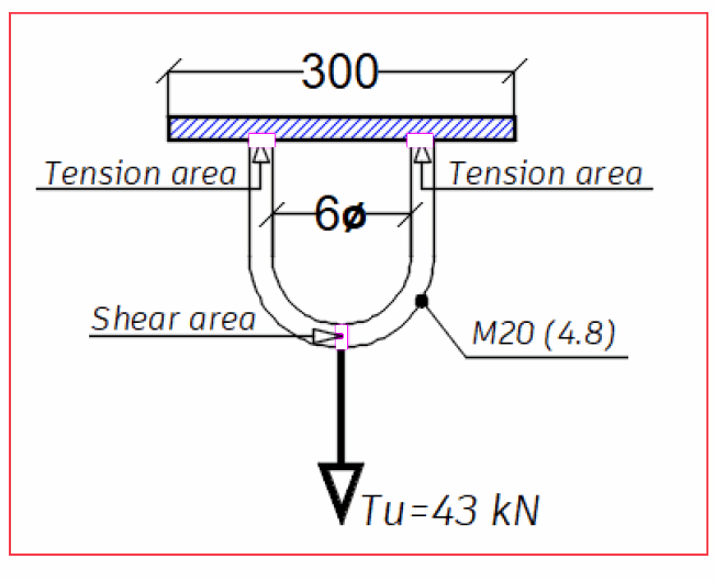
Reference to the following case which represents a chain-block as per the next screenshots
failure will be due to direct shear not tear-out and it seems that the plain rod in this case may be considered as a connected part.
shall i consider the total load = 43kN when calculated the required shear strength or have of it ??

c2_uaqct5.gif
Chain-Block_grqr4o.gif
C1_nd6ijl.gif
 
The shear would be 43 kN / 2. Draw an FBD of the left half of the U-shape. Cut the FBD off just to the left of the Tu. The shear equals the tension in the leg.

This looks more like a "threaded part" to me. That would be covered by Table J3.2, last couple of entries toward the bottom, and Eq. J3-1.
 
I have used a plain rod not a threaded rod to escape from using equation J3-1
 
Dear Ayman
you should Not worry too much about which equation controlling the design (shear or tensile stress)
in fact, you should worry about two things here;
1- the anchoring RAWLBOLTS
since they could easily break-through (mostly made be cheap metals)
so small advice, is to extend the anchoring to penetrate the roof (RC SLAB) so you could use a suitable anchors with enough(guaranteed) axial tensile capacity to prevent any failure due to (sudden impact or bouncing of lifted load ... etc)
2- the welding type around/between the U-shape hook legs and base plate ???
3- the plate metal type ???
 
Thanks I have respected all the points that you mentioned, however I need to use the suitable equation (understanding the code well)
I have posted my question in AISC and i am waiting for their reply.
Thanks for your support.
 
Status
Not open for further replies.

Part and Inventory Search

Sponsor