Continue to Site

Eng-Tips is the largest engineering community on the Internet

Intelligent Work Forums for Engineering Professionals

  • Congratulations SSS148 on being selected by the Eng-Tips community for having the most helpful posts in the forums last week. Way to Go!

The effect of drawing views on FCF/basic dimension placement 2

Status
Not open for further replies.

Nereth1

Mechanical
Feb 2, 2014
136
This seems like an extremely elementary question but I haven't been able to find anything explicit on it.

I always thought it didn't matter which view you place your FCF or basic dimensions on (other than for clarity), but I'm coming across a specific problem with that thought (axis parallel to another axis in one view, angled to it in another. Both need tolerancing)

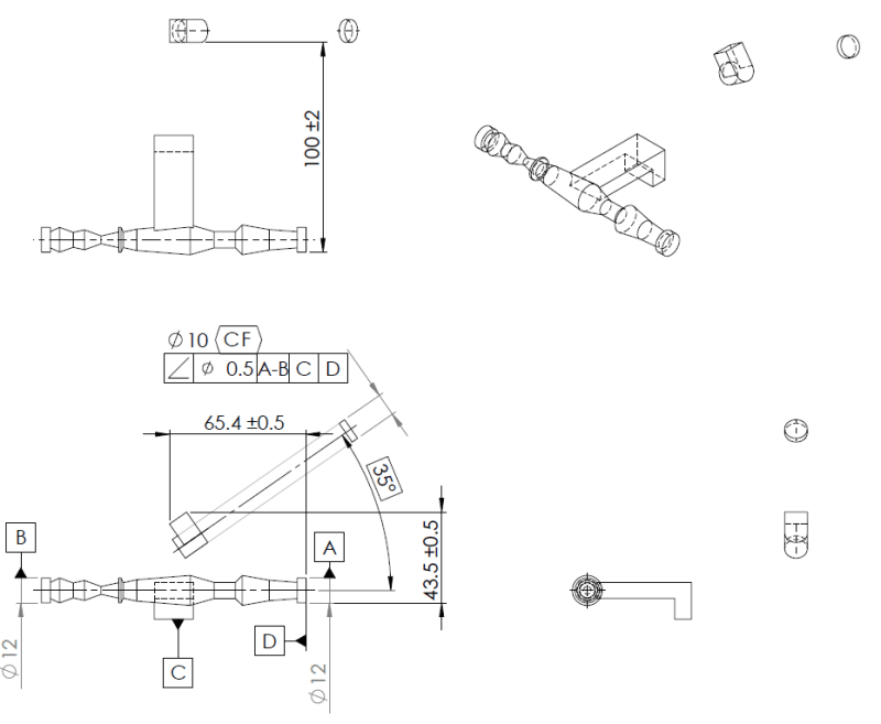
For example, if you put an angularity FCF on an axis, with the basic dimension between itself and a plane, and reference that plane as the datum, are you creating a conical tolerance zone or a planar one? If it is planar, who defines the plane that it is orthogonal to, other than the direction of the drawing view itself? You could include that plane in the FCF, but there is no way to say you mean that the basic dimension is measured on a plane normal to that plane, since basic dimensions themselves don't have reference frames.

Figure 6-6 and 6-7 in Y14.5-2009 appear to implicitly address this.

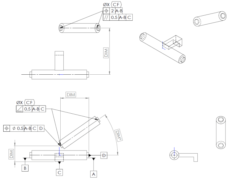
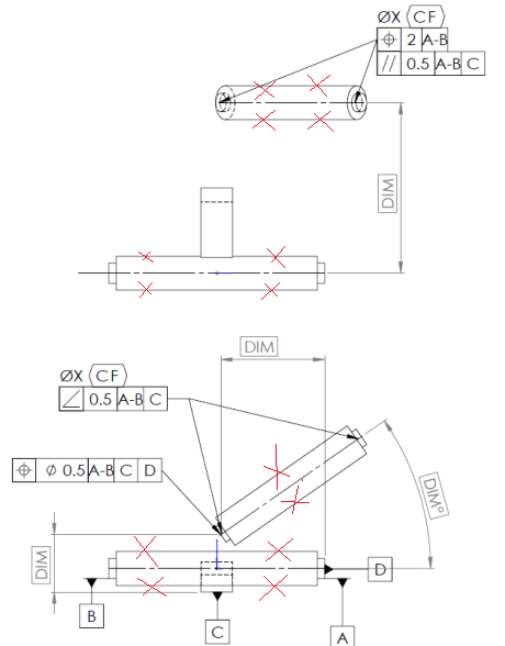
6-6 shows a diametrical tolerance zone created by an angularity FCF with only one datum plane. The implication is that the tolerance zone runs parallel to the plane of the drawing view (perpendicular to the viewing direction).

6-7 shows that by excluding the diameter symbol, you create two planes to define the tolerance zone, which again are projected along the viewing direction.

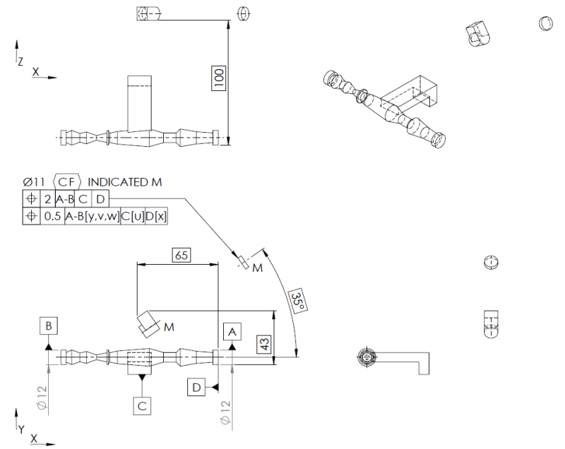
Ultimately I have an issue where I can use this quirk to solve my issue where I need parallelism of an axis to an axis in one view and angularity to that same axis in another (whereas if view doesn't matter, you can't have both parallelism and angularity of the same two axes to eachother, and then I don't know what to do), but using GD&T in this way (assuming that the view matters) does add a lot of other questions:

1) Am I about to create a whole bunch of confusion? Or is this something everyone else already knows about, and I'm just late to the party?
2) Who defines the reference frame for the view and the tolerance on that?
3) Is the implication here that FCFs in general only apply to basic dimensions that are in the same view that they are placed on?
4) Does the view matter with other controls? For example, position? If I want strong control of true position on 2 axes and weak control on another, can I apply an FCF with a tight tolerance in a view with those basic dimensions, and the FCF with the weak tolerance on a view with that basic dimension?

Thanks very much.


Replies continue below

Recommended for you

I think the key to answering your question is twofold: whether a diameter symbol is given in front of the tolerance number or not, and also what datums are being referenced. Notice in Fig. 6-7 there is no diameter symbol. Thus, the zone is planar. However, in Fig. 6-6 there is a diameter symbol in the FCF, giving the tolerance zone a cylindrical shape. In both of those figures, there is only one datum referenced, and it happens to be a plane. So you would think that in both cases the axis can tilt in and out of the picture without being noticed by the angularity tolerance.
One hitch in Fig. 6-6, however, is that if another view is given showing the hole as orthogonal to the other faces, then there is an implied perpendicularity which might come into play. (Fig. 6-7 doesn't have to worry about that, if we assume that the hole is going through a cylindrical post.) Obviously, more info is needed on the drawing to run with that idea.

BTW, with GD&T there is almost never a conical tolerance zone as you mentioned. The only time I can think of that would be the case shown in Fig. 7-27. But for your question I don't think we would go down that road.
 
Hi Belanger,

I agree that I have very rarely seen a conical tolerance zone (and it's obvious when they exist) - but as you mention, the only way to not create one with angularity to one plane, is to imply perpendicularity to the viewing plane, but the viewing plane is not controlled. Or you can have another datum to show the perpendicular plane - but there is no way to show that is what you intend to do with that second datum.

In my case, I do have a case where there is perpendicularity shown in another view, but as you mentioned, this is all implied stuff. Is that acceptable and normal? It gets hairier when we add some more of my issue - a position tolerance.

I can't provide the actual drawing for IP reasons, but I can create an analogous one - this is a fabricated assembly with some interrelated parts but some set reference points. It doesn't involve magical floating parts in the real world but the missing connections are irrelevant to the tolerancing.

GD_T_xkgnci.png


The intent here is to do the following:

1) reference axis is the horizontal one (formed by A-B), controlled axis is the inclined & offset one formed from the continuous feature defined between the ends of that shaft.
1) Control the orientation of the controlled axis within 0.5mm to A-B
2) Control the position in top view of the axis from the other axis to within 2mm of distance, i.e. within a 2mm projected plane from the viewing plane compared to A-B.
3) Control the position of the axis in the other two directions within 0.5mm - i.e. create a cylindrical tolerance zone at a specific measurable point on the axis (the lower reference point), projected from the viewing direction, into the page. This is reliant however on the user not combining the position tolerance in front view with the basic dimension provided in top view that was used for the 2mm FCF in top view. If they do combine them, this tolerance zone starts to control into the depth of the page which is not intended. Is the fact that I did not indicate a spherical diameter (SØ) sufficient to prevent this interpretation?
 
Wow theres a lot to unpack here, including a lot of misunderstanding.

Nareth1 4 Jan 19 01:58 said:
2) Who defines the reference frame for the view and the tolerance on that?
Huh? I think this comes from a misunderstanding about drawing views and their relationship to GDnT. See below.

Nareth1 4 Jan 19 01:58 said:
3) Is the implication here that FCFs in general only apply to basic dimensions that are in the same view that they are placed on?
No. All basic and toleranced dimensions for a given feature apply to the FCF for that feature, as dictated by the rules of the tolerance applied as well as the datums referenced unless otherwise noted.* It has nothing to do with what view it is applied on except in a select few cases** - though of course the designer should choose the view to a apply a tolerance/FCF which most clearly communicates their intent.

Nareth1 4 Jan 19 01:58 said:
4) Does the view matter with other controls? For example, position? If I want strong control of true position on 2 axes and weak control on another, can I apply an FCF with a tight tolerance in a view with those basic dimensions, and the FCF with the weak tolerance on a view with that basic dimension?
No (EDIT - except in a select few cases**). See above.


In regards to your second post, I don't know if its just the fact that I haven't had my daily dose of caffeine yet but I'm having a hard time following your thought process. I hope I'm not being rude when I say though that I don't think its necessarily worth addressing all those points in depth because I think your questions stem from a misunderstanding about how tolerance zones are constructed, which I addressed above.

I will however say that there are several issues with the sample drawing you provided. Not a single FEATURE Control Frame is applied to a FEATURE - they are all applied to theoretical points and axes instead of the FEATURE from which those are derived. Also your [A-B] datum is not derived like you think it is, again to create an axis A and B would have to be applied to the FEATURE(S) from which that axis is derived, not a theoretical axis (See Fig. 4-24). As they are shown I think the implication is that they are tangent to the features, but that is ambiguous and not clearly defined.

NOTES:
*An example might be composite tolerance where the basic dimensions relating a pattern back to the DRF do not apply in the lower control frames even when that particular DRF is referenced, though this is due to the rules of composite tolerance not what view it is applied in.

**Straightness applied to a planar surface (Fig. 5-6) and surface elements (Fig. 5-1) being one, and orientation of surface elements (Fig 6-16/6-17) being another. These are very specific cases though.
 
Nereth1,

You cannot apply an FCF to an axis. You apply it to a feature. If you are centreing that big cylinder to the hubs on either end, you apply the FCF to the cylinder. Your axis is defined by datum features[ ]A and[ ]B, not the big cylinder.

FCFs are applied to features, not construction lines.


--
JHG
 
Nereth1 said:
...I have very rarely seen a conical tolerance zone (and it's obvious when they exist) - but as you mention, the only way to not create one with angularity to one plane, is to imply perpendicularity to the viewing plane...
No, in any instance we are dealing with, the tolerance zone will never be conical. Let's just pretend that aspect of the discussion never came up :)

Like the other posts mentioned, the FCF shouldn't point to a center line etc. But to get to the heart of your dilemma, I think having the secondary datum C in the angularity callout satisfies your concern. The angularity tolerance will control the DIMº that you have as basic from A-B in the main view, and will also control the implied 90º (implied as basic) relative to datum C in the right-hand view.

But actually: you've also got a position tolerance in the main view of the same value (0.5 mm). That already controls orientation -- so you don't even need the angularity. That position also trumps the 2 mm position in the top view. So I think you've overcomplicated things?
 
Belanger said:
whether a diameter symbol is given in front of the tolerance number or not, and also what datums are being referenced


chez311 said:
I think your questions stem from a misunderstanding about how tolerance zones are constructed,


May I ask a question (a more general one) because, YES, I do have a gross misunderstanding about how the tolerance zones are constructed?

Which of the factors below are preponderant and most influential to get the correct tolerance zone SHAPE:

- Shape/form of the feature controlled
- order of precedence in the datum reference frame
- degrees of freedom constrained
- shape/form of the datum features referenced in the FCF
- view dependency and drafting
- all the above


In other words, are you thinking that the shape (not the size) of the tolerance zone is altered based on the datum features selection in the datum reference frame?

If yes, could you, please provide more details.
 
If the diameter symbol is given, then the tolerance zone is cylindrical. If the diameter symbol is not given, then the tolerance zone is two parallel planes (or two parallel lines). Of course there are exceptions to this, such as a spherical tolerance zone (Fig. 7-35), a conical zone (Fig. 7-27), a boundary of an irregular shape (Fig. 7-34), and of course profile (which can follow any shape).

But you ask, which of the listed factors determine the tolerance zone shape? One huge factor is the diameter symbol, but limited to the choices you give I would choose the first (shape of the feature). An example would be profile tolerances: the shape of the zone conforms to the true profile. The other things you list speak to how that zone is constrained in the bigger picture.

So if I may articulate your concern differently: You are concerned not so much with the shape of a tolerance zone itself, but how a tolerance zone can float in a bigger picture. For instance, in Figure 6-6 that you brought up in the original post, the tolerance zone is cylindrical. Period. That cylindrical zone may float in and out of the picture, but the zone is still cylindrical!

It's akin to bonus tolerance vs. shift tolerance: Bonus tolerance changes the tolerance zone itself (it enlarges). But shift tolerance does NOT change the zone in terms of its size or shape; it simply allows the zone to float/shift within other parameters.
 
Hi all,

I need to start by clarifying the drawing as some of the concerns raised I think come from the lack of clarity of my analogue:

a) In the real world there is no thick shaft linking the two smaller journals at the end - this is a separate component (not present at the time of gauging) linking them, the assembly of which is what causes the need for these controls on the journals. In the drawing my intent is that the FCFs are not applied to the axis of the shaft, they are applied to those journals at the ends of the shaft, which are then treated as a continuous feature to create the 'axis' (in the real world the gauge that checks them is an axial bar that drops in between them).
b) Note the 0.5 position tolerance in front view, is only on the lower journal, not on the axis, and not on the upper journal. So it positions the lower journal, then the angularity which applies to the lower and upper journal as a continuous feature, effectively serves to locate the upper feature relative to the lower feature. I could likely also have used composite position but angularity gives more clarity I think, because the written spec I am trying to match with the drawing is given in terms of angles and parallelism of the axis between those journals, not relative position of the upper journal to the lower journal.

See new drawing below (no CAD program at home to update this unfortunately:

GD_T_markup_yvnl53.png


Now to respond to individual posts:

chez311 said:
No. All basic and toleranced dimensions for a given feature apply to the FCF for that feature

This is the crux of the issue - I would have said the same until two days ago until I came across this problem and thus posted this question - can you tell me how to interpret figure 6-6 and 6-7 in Y14.5, without looking at is a conical tolerance zone then? These images show angularity of an axis to a single reference plane. There is no orthogonal reference plane from which to take a 'slice' out of that cone.

chez311 said:
I will however say that there are several issues with the sample drawing you provided. Not a single FEATURE Control Frame is applied to a FEATURE - they are all applied to theoretical points and axes instead of the FEATURE from which those are derived. Also your [A-B] datum is not derived like you think it is, again to create an axis A and B would have to be applied to the FEATURE(S) from which that axis is derived, not a theoretical axis (See Fig. 4-24)

As explained above all of the tolerances and references are applied to the journal features in the drawing, not directly to axes. Apologies for the lack of clarity, I should never have included the central shaft in the drawing (which doesn't exist in real life).

Belanger said:
I think having the secondary datum C in the angularity callout satisfies your concern. The angularity tolerance will control the DIMº that you have as basic from A-B in the main view, and will also control the implied 90º (implied as basic) relative to datum C in the right-hand view.

So this is again a very important point - we are saying that the angularity tolerance in front view it would control the angle in top view implicitly. In that case the parallelism tolerance is plain wrong (because it's parallel in top view but not in 3 dimensions), but the angularity tolerance can be used on its own to control orientation on all 3 degrees of rotational freedom. So we just delete the parallelism tolerance.

Then this leaves how we achieve position tolerance on two axes to 0.5mm and on the third axis to 2mm, since the position FCFs can't be written to do that within the 4 reference surfaces I have (I can't think of a way anyway, datum C is not a reliable height datum, it can only be used to set the angle around A-B). I suppose I would just remove the position tolerances entirely, then tolerance the lower journal with conventional +/- tolerancing to the reference points, putting +/-0.5 on the front axis dimensions and +/-2 on the spacing in top view?
 
Belanger said:
If the diameter symbol is given, then the tolerance zone is cylindrical. If the diameter symbol is not given, then the tolerance zone is two parallel planes (or two parallel lines). Of course there are exceptions to this, such as a spherical tolerance zone (Fig. 7-35), a conical zone (Fig. 7-27), a boundary of an irregular shape (Fig. 7-34), and of course profile (which can follow any shape).

But you ask, which of the listed factors determine the tolerance zone shape? One huge factor is the diameter symbol, but limited to the choices you give I would choose the first (shape of the feature). An example would be profile tolerances: the shape of the zone conforms to the true profile. The other things you list speak to how that zone is constrained in the bigger picture.

So if I may articulate your concern differently: You are concerned not so much with the shape of a tolerance zone itself, but how a tolerance zone can float in a bigger picture. For instance, in Figure 6-6 that you brought up in the original post, the tolerance zone is cylindrical. Period. That cylindrical zone may float in and out of the picture, but the zone is still cylindrical!

It's akin to bonus tolerance vs. shift tolerance: Bonus tolerance changes the tolerance zone itself (it enlarges). But shift tolerance does NOT change the zone in terms of its size or shape; it simply allows the zone to float/shift within other parameters.

Another very important point you raise here Belanger, and it makes sense to me, but the implications seem confusing.

If we look at the position tolerance on the lower journal on my drawing, and lets pretend that tolerance was applied to a vertex at the end of that journal so we could measure a discrete position from it in 3D space.

Then if I put a a Ø0.5 position tolerance to A-B, C, D in front view, am I:

a) Creating a cylindrical tolerance zone projecting from front view, controlling only left/right up/down but not into and out of the page
b) Writing an invalid FCF, which is where I feel like I am leaning here.

And thus, is the only option actually:

a) Use a spherical tolerance zone, which thus controls all 3 axes.
b) If I leave no indicator on the '0.5' tolerance, i.e. leave it blank, am I creating a cubic tolerance zone which also controls all 3 axes? But this does fly in the face of the 'two parallel planes' item you just mentioned, but perhaps just an oversight?
 
No, no, no. Position tolerance does not control a vertex, or a point, or anything like that in the example you are giving. The position tolerance controls the axis of the feature. (Why? Because the physical feature is itself cylindrical.)
So the position tolerance does not constraining a point at the end of the feature but the axis. So when you posted item (b) "Note the 0.5 position tolerance in front view, is only on the lower journal, not on the axis" that is not a statement that I can interpret in the language of GD&T.
 
Hi Belanger,

Agreed - that's what I meant by "let's pretend it was applied to a vertex", I understand that it won't do what I described on that journal because the journal doesn't have a single discrete position. I'm asking a question about the GD&T concepts you brought up about tolerance zones rather than specific to my example as drawn with it applied to the journal.

In reality there are some discrete faces and edges on that 'journal' that allow placement/measurement of position (not as simple as a vertex unfortunately).

A lot of these misunderstandings stem from my hashed together stand-in example. I did not think hard enough about that before I made it.

In light of this are you able to provide comment on my earlier questions? I think that would be very helpful to me to confirm what I have taken from this discussion.
 
OK -- I didn't mean to jump on you about that, but I want to make sure that we agree on some of the basics of GD&T, such as where a tolerance zone resides.

To answer your questions, here's one that I picked from above:
"In other words, are you thinking that the shape (not the size) of the tolerance zone is altered based on the datum features selection in the datum reference frame?"
My answer: No I am not thinking that the shape (nor size) is altered. What may be altered is how that tolerance zone floats within space. It might be fully constrained, or it might be allowed to scoot or rotate -- but that doesn't change the shape of the tolerance zone.

The reason... if we were to say that a tolerance zone's movement changes the size or shape, then that means the axis in question could weave all over the place within that "larger" zone. Instead, the axis in question must stay within the same size/shape (such as a 0.5 mm zone) yet the location or orientation of the axis to other datums would be a different question.
 
Nereth1 said:
In the real world there is no thick shaft linking the two smaller journals at the end - this is a separate component (not present at the time of gauging) linking them, the assembly of which is what causes the need for these controls on the journals. In the drawing my intent is that the FCFs are not applied to the axis of the shaft, they are applied to those journals at the ends of the shaft, which are then treated as a continuous feature to create the 'axis' (in the real world the gauge that checks them is an axial bar that drops in between them)
I know you have said that perhaps your drawing created some confusion but I just want to address that, none of the issues with your drawing had to do with the inclusion or omission of this central shaft - it was understood that you were attempting to control position/orientation of the two journals on either end, but you were doing so improperly. With or without it your FCF's are pointing to theoretical axes and points instead of physical features. See the difference below.

position_evooiz.png


Nereth1 said:
can you tell me how to interpret figure 6-6 and 6-7 in Y14.5, without looking at is a conical tolerance zone then? These images show angularity of an axis to a single reference plane. There is no orthogonal reference plane from which to take a 'slice' out of that cone.
Neither of those describe a conical tolerance zone. In both examples they are cylindrical zones that have unconstrained degrees of freedom due to a single datum in the DRF - as JP said that does not change the shape/size of the tolerance zone, only how it can move relative to the DRF. Additionally none of this has to do with what view it is defined in, but the datums referenced in the DRF.

Nereth1 said:
Then if I put a a Ø0.5 position tolerance to A-B, C, D in front view, am I:
Position is NOT view dependent - there are only a few set of circumstances where the view has any impact on the tolerance applied, I tried to state that in my previous post (and most of those cases could also probably be covered with phantom lines and custom notes instead if one were so inclined). It seems to me that since you are still mentioning views then this misunderstanding persists. A position tolerance could be applied to a feature in several different views, as long as the construction of the FCF and DRF was the same, and the intent was clear (ie: it was clear what feature it applied to and applied properly per Y14.5), they would describe the same tolerance zone.
 
Hi Chez311,

Yep I understand what you are saying about it needing to be applied to a feature - I got lazy because I didn't have a diameter dimension/callout on them, which is what I normally use for applying features to cylinders, and I didn't really think about it. Obviously this isn't ideal when using it as an example of GD&T for a discussion like this!

Regarding your second point, don't worry I'm not hung up on it being view dependant, you'll note my point B below that scenario was basically "I'm making a mistake aren't I". The point I was getting to (trying to confirm with you guys) is you can't really put a diameter symbol around a vertex, because the diameter symbol implies a cylindrical tolerance zone running in a certain direction based on the basic dimensions of the feature, e.g. the axis of a shaft, and a vertex doesn't have a direction. Whereas according to my previous understanding, the cylindrical tolerance zone would have been projected from the view to contain the vertex (clearly false)

To all contributors,

Thanks for the discussion, it has been very helpful getting me back on track with GD&T, unfortunately our company only cracks it out for major projects so I go 6-12 months at a time between serious usage and have to relearn a lot each time (and we don't have anyone else at all familiar with it, nor could I even find a consultant in our town). When I get into the office on Monday I will make a new tolerance scheme and post it (and fix some of my shortcuts in the example so that my usage is clear from the get-go) to confirm my 'new' understanding.

Just to clarify one last point based on this - is it impossible with position FCFs to put varying tolerances in different directions, unless you have available a set of datums that would allow you to have multiple position FCFs each only referencing datums that control the relevant axes to itself?

So, if you have 3 orthogonal datum planes A, B, C, you could use a position FCF 0.5mm to a and b, and separately, a position FCF 2mm to c, in order to create a tolerance zone that is a rectangular prism, 0.5mmx0.5 wide when viewed from C, and 2mm long normal to C?

But with the datums in my example above, since I can't create planes orthogonal to those relevant directions (c and d are both unreliable sources of 'normal' directions in the real part, they can only be used to lock position relative to the axis formed between a-b), I can't do the same (without conventional +/- tolerancing)?
 
Belanger said:
For instance, in Figure 6-6 that you brought up in the original post, the tolerance zone is cylindrical. Period. That cylindrical zone may float in and out of the picture, but the zone is still cylindrical!

May I ask, one additional question about Figure 6-6: why the tolerance zone for the orientation control/ angularity is cylindrical, when only one datum feature (only the primary) is specified? Why is not "width-shaped"?

What makes figure 6-6 different relative to figure 6-7, except it's not 90 degrees basic/ 180 degrees basic implied, but 60 degrees basic shown?


Kedu -- It's true that the tolerance zone for angularity in Fig. 6-6 is not constrained in other directions, but the caption clearly states that it is a cylindrical zone. So that's one reason why we know it is cylidrical. [smile]
Maybe think of a gage pin that would go into that hole to check the GD&T. It would have to be an expanding pin because it's RFS -- but the gage pin would be a cylindrical shape; maybe that helps visualize the reason for the diameter symbol. If it weren't cylindrical, would the gage pin be a diamond shape?

By the way, in studying those pages a little more, I did find a discrepancy between Fig. 6-6 and the text in paragraph 6.4.2(b). So if 3DDave is still keeping a list of goofs in the Y14.5 standard, he can add this: The paragraph describes how an orientation tolerance may be "two parallel planes" and it refers to Fig. 6-6 as an example. But the caption in that figure clearly describes it as cylindrical.
 
Hi all,

Does the below work better for everyone based on my prior stated intent?

GD_T_attempt2_lswgez.png


This doesn't seem terrible elegant to me but I can't think of a better way.

The obvious solution is to lock position 1mm (+/-0.5) of the lower journal to C & D, then 4mm (+/-2) to A-B, C, D, but the orientation of datum feature C and D are not good enough to create correctly oriented datum planes from on their own, so I can't actually establish a rotation of the datum reference frame without using A-B, the calling of which would then inherently make my +/-0.5mm position constraint also apply to the dimension that I only want to control to +/-2.

I'm currently reading for a solution in Y14.5, but ultimately it's probably not the end of the world to leave it as is.
 
OK - have just done some reading about custom datum reference frames, seems what I am trying to do is the below (I accept that there are some basic dimensions missing that would need to be added to clarify the real thing):


GD_T_DOF_removed_from_A-B_ehfiv4.png
 
It is not common to dimension to tangent silhouette edges; if the dimensions are between features of size the dimensions are to their centerlines. Likewise, not dimensioning to corners and edges, particularly of items that aren't otherwise constrained.

Create a view along the axis of the feature and put the orthogonal controls in that view.
 
Status
Not open for further replies.

Part and Inventory Search

Sponsor