Continue to Site

Eng-Tips is the largest engineering community on the Internet

Intelligent Work Forums for Engineering Professionals

  • Congratulations SSS148 on being selected by the Eng-Tips community for having the most helpful posts in the forums last week. Way to Go!

The effect of drawing views on FCF/basic dimension placement 2

Status
Not open for further replies.

Nereth1

Mechanical
Feb 2, 2014
136
This seems like an extremely elementary question but I haven't been able to find anything explicit on it.

I always thought it didn't matter which view you place your FCF or basic dimensions on (other than for clarity), but I'm coming across a specific problem with that thought (axis parallel to another axis in one view, angled to it in another. Both need tolerancing)

For example, if you put an angularity FCF on an axis, with the basic dimension between itself and a plane, and reference that plane as the datum, are you creating a conical tolerance zone or a planar one? If it is planar, who defines the plane that it is orthogonal to, other than the direction of the drawing view itself? You could include that plane in the FCF, but there is no way to say you mean that the basic dimension is measured on a plane normal to that plane, since basic dimensions themselves don't have reference frames.

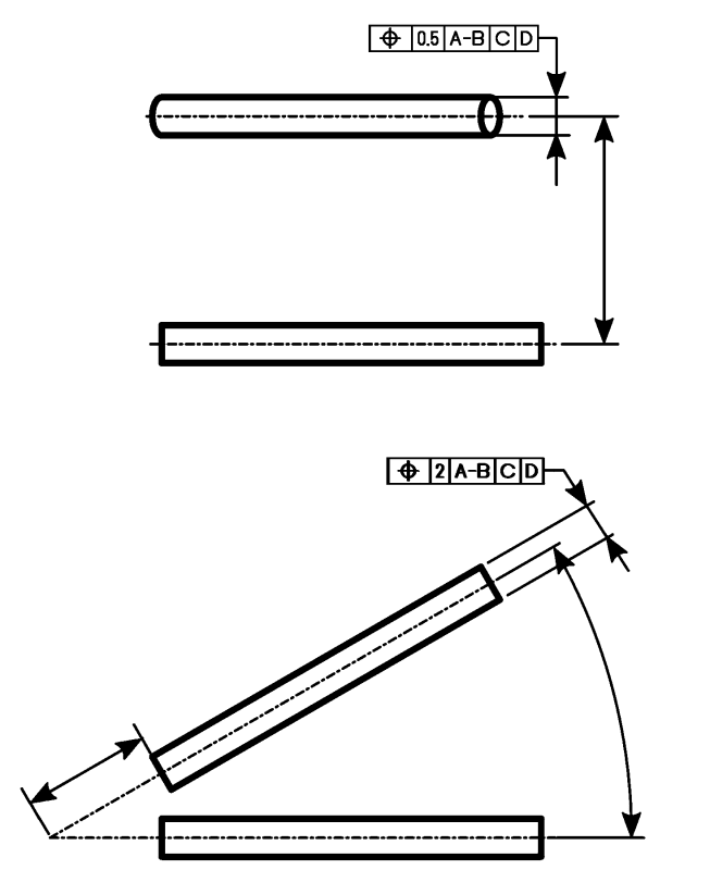
Figure 6-6 and 6-7 in Y14.5-2009 appear to implicitly address this.

6-6 shows a diametrical tolerance zone created by an angularity FCF with only one datum plane. The implication is that the tolerance zone runs parallel to the plane of the drawing view (perpendicular to the viewing direction).

6-7 shows that by excluding the diameter symbol, you create two planes to define the tolerance zone, which again are projected along the viewing direction.

Ultimately I have an issue where I can use this quirk to solve my issue where I need parallelism of an axis to an axis in one view and angularity to that same axis in another (whereas if view doesn't matter, you can't have both parallelism and angularity of the same two axes to eachother, and then I don't know what to do), but using GD&T in this way (assuming that the view matters) does add a lot of other questions:

1) Am I about to create a whole bunch of confusion? Or is this something everyone else already knows about, and I'm just late to the party?
2) Who defines the reference frame for the view and the tolerance on that?
3) Is the implication here that FCFs in general only apply to basic dimensions that are in the same view that they are placed on?
4) Does the view matter with other controls? For example, position? If I want strong control of true position on 2 axes and weak control on another, can I apply an FCF with a tight tolerance in a view with those basic dimensions, and the FCF with the weak tolerance on a view with that basic dimension?

Thanks very much.


Replies continue below

Recommended for you

Hi 3DDave,

Agreed on all points - the real part has a whole different set of non-cylindrical faces to use so I will be able to easily measure to them. I'm stuck between recreating the measurement points we have in real life yet not on something that looks like the real life part as it is commercially sensitive.

Is the tolerancing scheme itself technically sound however? Particularly in the second drawing as I feel that one better suits the fact that we are doing the checking entirely with a go/no-go jig that runs off the given reference faces.

Thanks
 
Nereth1 said:
The point I was getting to (trying to confirm with you guys) is you can't really put a diameter symbol around a vertex, because the diameter symbol implies a cylindrical tolerance zone running in a certain direction based on the basic dimensions of the feature, e.g. the axis of a shaft, and a vertex doesn't have a direction.
Again, I hope I'm not beating a dead horse but I think it needs to be reiterated - a position tolerance can only be placed on actual physical features. The only vertex I think I saw on that drawing was the intersection of a theoretical axis and planar feature. A theoretical axis is not a feature just as a theoretical vertex (formed by the intersection with a theoretical axis or plane) is not a feature (whether a physical edge or corner can be interpreted as an irregular FOS has been debated - this is a rabbit hole you don't want to go down, what you need to know is that Y14.5 does not provide a clear roadmap to interpret these features). The axis of a cylindrical feature is controlled because it is derived from that cylindrical feature.
 
It doesn't matter that there are non-cylinders - it matters that the dimensions locating the cylinder needs to go to the cylinder axis.

Is there a reason not to create a view looking along the axis with separate callouts for the tolerance zone in the orthogonal directions? As it is you create two different DRFs to control one axis when only one DRF is required. Seems expensive.
 
What I meant by non cylindrical is that I have actual flat faces to dimension to, so I haven't thought that hard about the cylindrical analogue. I can only apologize for the amount of everyones time that that decision has wasted as you have all noticed it and raised it. Similarly the only reason for the lack of thought/poor placement of basic dims and lack of an end-on view was to save time in whipping up the drawing, as I'm really not trying to delve into those items in this case, I'm rather trying to understand tolerance zone shapes etc.

I have to redo the whole thing for the actual part once I confirm my understanding of FCFs/reference frames, and that will also comes with a lot of extra thought not just about basic dim placement etc, but about what is and isn't accessible and measureable on the real part.

The key outstanding question is if anyone can confirm that I have correctly used the position tolerance in a way that prevents the 0.5 line from effecting the position of the axis in the Z direction. This is something I have never done before so I am apprehensive about jumping right in.

Thanks

 
Presently the top control is in one, unspecified direction. Aside from that, sure. If it was a diametral zone it would control an axis.
 
OK that's helpful - two queries:

1) I thought that the top control was in all directions, but overridden by the tighter bottom control in all but Z (which is excluded from the bottom control). Am I reading it wrong?
2) I am trying to control the position of that axis, but was attempting to create a tolerance zone that is a rectangular prism (made up of 3 sets of parallel planes), rather than a cylinder, by omitting the Ø symbol. Is that incorrect?
 
1) Yes. Each requirement is entirely separate, evaluated as if the other does not exist.
2) Yes. From what you have now there is no possible third pair of planes.

The basis of true position tolerancing is that there is an ideal location specified by basic dimensions, either explicit or (in the case of colinear items) implied. The tolerance is the amount one can vary from that ideal location. If there is a need for an orthogonal set of controls, there needs to be an identification of the exact direction that the control applies in; trying to backdrive that by changing datum references is problematic because it does not directly change the size or shape of the zone, just where the zone can be.

Using a single leader will not perform the task of identifying a direction for the related zone and it will be applied to the feature width to do so, so there will be two opposing arrows.
 
I'm not quite sure I understand - but is the overarching problem that my dodgy basic dimensions don't allow my FCFs to make sense? I will remake the drawing now and post shortly, assuming that is the issue.

Edit: Ah - I understand the issue now, I have overlooked a lot of the positional requirements because I wasn't planning to position it along its own axis with the GD&T. But I've made a hash of even that because 'it's own axis' is a combination of two of the axes that I have controlled.

This is frustrating because I can imagine the gauge, the pickup points, the measurement points, but I can't imagine the solution of how to dimension it in space outside of basic dimension to vertexes or virtual points (neither of which are preferred it sounds like?).
 
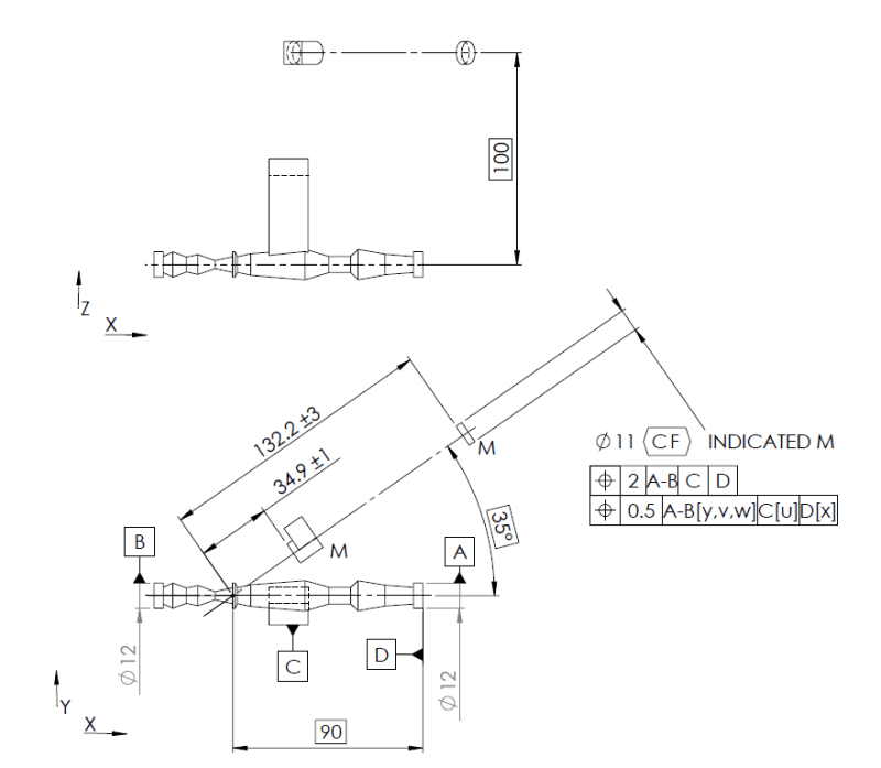
OK - Based on figure 7-36, one solution would be to control the axis by attaching the X & Y basic dimensions to the theoretical intersection point of the controlled axis and some specific plane (perhaps the plane established by A-B & C, and position it in top view to get its offset along Z? Then I can add conventional +/- dimensions to position each individual journal in the continuous feature, along the axis length (which is what I intended to do on the real part anyway as they have different tolerances and should slide along the part in some cases) This would look like the below. Thoughts would be greatly appreciated:

GD_T_test3_cmsgey.png
 
Let me draw this for you then. (imagine that I duplicated the candlestick details and the tab and placed the datum feature symbols.)
nereth_ay4c8r.png
 
That was more or less what I did originally - but isn't the result of this discussion that I was wrong, and that both of those FCFs will apply to all of the basic dims on both views, thus the 0.5 FCF would rule (they are both active but the 0.5 FCF makes the 2 FCF become redundant) and you would just be controlling position to 0.5 on all axes?
 
The leaders never gave a direction. There is no interpretation for what you did earlier. You are free to create your own schemes, but it would be nice to leave Y14.5 off the drawing and explain directly to whoever is depending on this work what you mean. I believe what I put up is explained in the many versions of the Y14.5 standard.

If there was a diameter symbol associated with a tolerance, that would make a difference, but without it, each of the FCFs controls a width.
 
Are you saying my original scheme would have worked if the FCFs, datum features, and basic dimensions were to valid points? But my understanding was the entirely unsolveable issue with that scheme was that the FCFs always apply to every dimension in every view that is on that feature?

If that is not true, can you explain to me how your tolerancing scheme defines the axes/directions to which each FCF applies? Or perhaps point me to where in Y14.5 I should be reading for that info? Because I originally tried to find some reference to this and couldn't (which is why I made this thread)

By the way, regarding leaving Y14.5 off the drawing and just explaining directly - agreed, this is a large project and the gauging requirements and methods have already been agreed upon by all parties. But we just need a way to document it. "If in doubt, write it out" is certainly an option that may come up soon, but that could take paragraphs and paragraphs to eliminate ambiguity, and I feel like I am on the cusp of understanding how to do this properly...
 
I have to apologize to you Nereth1. I had not considered bidirectional tolerancing in my initial statement, and by extension had not considered it view-dependent, especially since the two examples in the standard are provided in the same view. I see now that bidirectional tolerancing (or for that matter, tolerancing of non-planar/round features with a non-cylindrical/planar zone) is view dependent insofar that the combination of the view it is specified and the direction of the width leader lines define the location/shape of the tolerance zone. If you had included a diameter symbol my original statement would stand.

Note that the same bidirectional tolerancing could be accomplished, albeit slightly less elegantly, by providing a view normal to the flat end face of the feature of interest and providing the same 0.5/2 width position tolerances in the directions desired.

For some (limited) information on bidirectional tolerancing see section 7.4.4 and Fig 7-28/7-29. There are also some examples of dimensioning round holes with planar/width shaped tolerance zones - of which bidirectional tolerancing seems to be a natural progression of that concept.

If 3DDave/JP or others would like to chime in with some additional tolerances that can be view dependent I would be interested to learn of them so I won't make the same mistake in the future (I had already mentioned straightness applied to a planar surface (Fig. 5-6) and surface elements (Fig. 5-1) being one, and orientation of surface elements (Fig 6-16/6-17))
 
Haha, yep, bidirectional tolerancing is what I need, it's the right way to do what I was originally attempting to do with views.

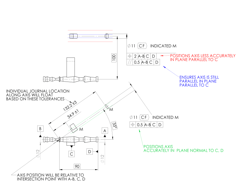
I've also realised my tolerancing system above misses the refinement on parallelism that I need in the X/Z plane (i.e. in top view/A-B, C). I assume a bidirectional position tolerance can also be refined by a parallelism tolerance that would follow the same rules (i.e. not accidentally specify that the two axes be completely parallel in all planes)?

Edit: In other words, does the below all mean what I think it means?

GD_T_test_bidirectional_lqp5ub.png
 
Nereth1,

The bidirectional tolerance FCFs are supposed to be attached to dimension lines, not placed below feature size dimensions. For maximum clarity, I'd recommend duplicating ASME Y14.5-2009 Figs. 7-28 and 7-29 as closely as practical.

I think changing your blue tolerance from parallelism to angularity would make it somewhat less controversial.


pylfrm
 
Nothing really specifies, unless there is a note, the significance of an intersection relative to the plus-minus tolerances. There are a number of co-axial features involved, any combination of which might serve the purpose. If you want to control where the end faces are use a profile control and use explicit datum references.

Angularity vs parallelism** might confuse the issue because there is no angle explicitly stated except inclination to the plane that datum_feature A-B lies on and oriented by the reference to datum feature C. However, there's no value in having a reference to datum feature D in that control.

Also, typically, the size dimension is only called for once, so that is often independently placed from the tolerances, making the standard defined method I showed and pmarc described the only one available in 2D drawings per Y14.5.

If the feature turns out to be rectangular, a case that would co-locate the FCF, that would be different.

Also, just to tweak this, datum feature C really needs a profile control relative to datum A-B and would probably benefit from the [BSC] modifier to simplify the gaging of dependent features, unless the mating installation has a tiny elevator platform to adjust the location. For sure, given the tiny foot print, it is not useful as a stable datum reference for controlling orientation about A-B.

**Has the new version eliminated everything in favor of heavily context dependent profile of surface and profile of line tolerances yet? Once the Angularity/Perpendicularity/Parallelism is compressed it's easy to see the survivor is just a special case of some form of profile as are runout and cylindricity, et al.
 
I like where we are at now - I feel like I am on the same page as you both and actually understanding the feedback I am getting from you for the first time in the conversation :)

pylfrm:

Bidirectional tolerances to dimension lines - This didn't click to me on first read through, but yes you're right. Will make that change on the real part.
Parallelism vs angularity - since you think parallelism and 3DDave seems to think angularity "less controversial" appears to be the only thing we will end up shooting for here. I think angularity may be technically correct (it is at an angle), but parallelism might be more clear?

3DDave:
Using the intersection for the plus minus tolerances: I assume this is OK for the axis location but not so great for the positions of the faces along the axis? What you have suggested makes sense for this part for sure. On the real part I will have to think about it. Those axial locations are traditionally (for this type of product, and in this industry) measured with a tape measure and to a point that isn't actually on that axis in the first place. So whether I do what is probably best practice or what is common practice is a decision I will have to make.
Angularity vs parallelism: As mentioned I can see both points of view.
Calling size of the diameter twice and combining with the bidirectional FCFs: Yep, that's a newbie error of mine I like to think I wouldn't normally make.
Datum feature C: I had been thinking about using the [bsc] modifier as I saw it while reading through constructing datum frames and it looked appropriate. But I didn't want to throw it into this drawing as it would be the first time doing it and didn't want to add more mistakes to the pot. The real part has a half-cylindrical surface for that gauge point, but it's axis is coplanar with the plane I am trying to create, rather than being offset, so it's a bit different again. I figure the diameter tolerance should handle its profile and I think a cylindrical datum rotating about an axis parallel to itself will make [bsc] redundant? Since there is no way to make more 'maximal contact than however it lands on the gauge. Although possibly [bsc] on the top-view offset will be called for instead.

Thanks!
 
Status
Not open for further replies.

Part and Inventory Search

Sponsor