There are two questions about the curve of load and displacement and one question about deformation result for FEM ,
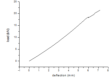
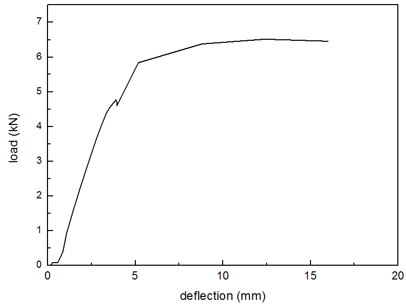
1. the load obtained by displacement controlled in abaqus is larger than experimental result, although the material elastic property is same as description in the literature, of course, there is some simplification in my model.
2. Beside, I use nonlinear analysis due to big deformation, nut the curve of load vs displacement is not nonlinear at the displacement between 6mm and 8mm. After the 8mm, abaqus is terminated due to many attempts. At last, I must mention that the material has plastic characteristic, but due to lack the value of stress and strain, I ignore them.
3. The specimen is sandwich composite consisted of two skins and core, but the deformation of bottom skin seem not occur, but the experimental result has small deformation at this deformation at relevant displacement.
4. The region of distortion will be corrected by re-drawing more tiny mesh, if you think it's wrong, please tell me. Due to lot time to recalculate it, so I plan to wait to solve above problems.
FEM: load vs displacement

experiment: load vs displacement

FEM: deformation result:

1. the load obtained by displacement controlled in abaqus is larger than experimental result, although the material elastic property is same as description in the literature, of course, there is some simplification in my model.
2. Beside, I use nonlinear analysis due to big deformation, nut the curve of load vs displacement is not nonlinear at the displacement between 6mm and 8mm. After the 8mm, abaqus is terminated due to many attempts. At last, I must mention that the material has plastic characteristic, but due to lack the value of stress and strain, I ignore them.
3. The specimen is sandwich composite consisted of two skins and core, but the deformation of bottom skin seem not occur, but the experimental result has small deformation at this deformation at relevant displacement.
4. The region of distortion will be corrected by re-drawing more tiny mesh, if you think it's wrong, please tell me. Due to lot time to recalculate it, so I plan to wait to solve above problems.
FEM: load vs displacement

experiment: load vs displacement

FEM: deformation result:


