Navigation
Install the app
How to install the app on iOS
Follow along with the video below to see how to install our site as a web app on your home screen.
Note: This feature may not be available in some browsers.
More options
Style variation
-
Congratulations MintJulep on being selected by the Eng-Tips community for having the most helpful posts in the forums last week. Way to Go!
You are using an out of date browser. It may not display this or other websites correctly.
You should upgrade or use an alternative browser.
You should upgrade or use an alternative browser.
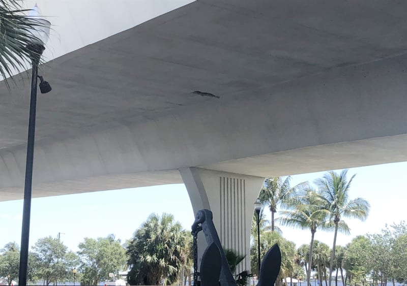
The Roosevelt Bridge, Stuart, FL
- Thread starter wiktor
- Start date
- Status
- Not open for further replies.
LittleInch
Petroleum
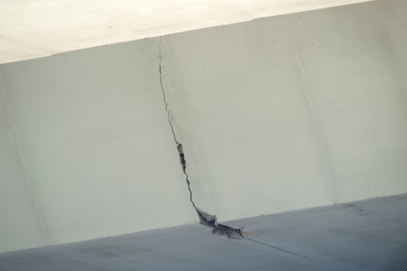
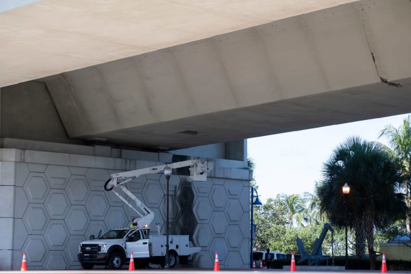
Some better pictures here.
Imminent collapse looks a bit strong, but for sure, its splitting along what looks like a construction seam. Was this a post tensioned beam structure?
Precast hollow box sections apprently
Can't see how the segments were connected, but there is a hollow road inside apparently with two golf buggies to drive up and down!
Remember - More details = better answers
Also: If you get a response it's polite to respond to it.
- Thread starter
- #3
Yes, it's a segmental box bridge, post tensioned, the segments were match casted and connected using grout and post tensioning. Looks like some of the bottom cables have corroded, and the span is ready to go..
The entire cross section shall be always in compression, so any crack appearing calls for emergency shoring and closing of the bridge.
The entire cross section shall be always in compression, so any crack appearing calls for emergency shoring and closing of the bridge.
I'm a long way from an expert on this but... I'm seeing both cracking on the tension flange mid span and potential cracking on the tension span above the supports.
- Moderator
- #5
I grew up in Stuart, home to I believe 4 segmental box girder bridges, and this is causing a traffic nightmare for my family.
Nothing seems obvious from the crack pattern. Could simply be spalling. It’s in the right spot to be a flexural crack, but as Wiktor said above, the whole thing should be in compression. But I’m not a bridge guy, and these segmental box girder bridges are a real specialty. I found some good general info here:
If this ends up being serious, I hope that laws change to require additional scrutiny of the design and construction of PT structures, generally.
Difficulties with the quarter-point detail in balanced cantilever construction led to another
construction approach to providing expansion joints in long structures of long span lengths.
This method calls for placing expansion joints over the piers and temporarily stressing the
expansion joint segments together to form a single pier segment. The segments on either side
of the expansion joint are then placed in cantilever until the adjacent mid-spans are reached.
Once closure joints are poured and continuity tendons stressed, the cantilever tendons through
the expansion joint segments are removed and the two expansion joint segments separated
from each other to allow the necessary thermal and long-term movements. This method of
construction was used at the Roosevelt Bridge in Martin County
- Thread starter
- #10
The locations of the cracks at the segments' joints may indicate corrosion of the "stiff" reinforcement located too close to the segment edge, causing the spalling.
Unfortunately I do not have the drawings of the bridge anymore, but some years ago these were used as a guide to design similar bridge in the Northeast, and definitely there were no problems with the design - so the bridge is not a Miami Pedestrian design disaster with the SF<1.3 at the construction stage, and 1.45-1.5 fully assembled.
But the problems with poorly ventilated enclosed box girders are well known, and exacerbated by the marine environment may lead to accelerated corrosion. The integrity of the of the cement grouting protecting the post tensioning strands is the main concern.
The bridge was erected by the balanced cantilever method, so each segment has some post-tensioning cables terminating at the joints, and change of the design moments and normal forces.
The photographs posted are not of the highest quality, so is difficult to asses the exact nature of the cracking, and distinguish in between spalling (local corrosion) or major problem.
But if the cracks were through and also present at the inside of the box, the entire bridge should be closed and carefully inspected.
- Moderator
- #11
In Central America concrete was typically mixed and placed with a great surplus of water.
This left the concrete porous and subject to rebar corrosion.
It was not uncommon to see the underside of second floor slabs with all the concrete spalled off of the rebar.
It didn't help that the rebar was typically very close to the bottom form.
Given the stain patterns along the span, my first guess would be spalling due to rebar corrosion.
If left unattended I would expect some of the other stain marks to develop similar spalls within a few years.
If this is spalling the crack may terminate at the rebar.
Bill
--------------------
"Why not the best?"
Jimmy Carter
Imminent collapse does seem a little over blown. But I'll go with flexture cracking more than corrosion spalling. There are 3 different large cracks in this section two in zones of tension, one in a zone of high shear.
And at least one of the cracks isn't new. This is 13 months ago from google maps.
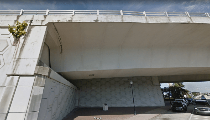
And at least one of the cracks isn't new. This is 13 months ago from google maps.

LittleInch
Petroleum
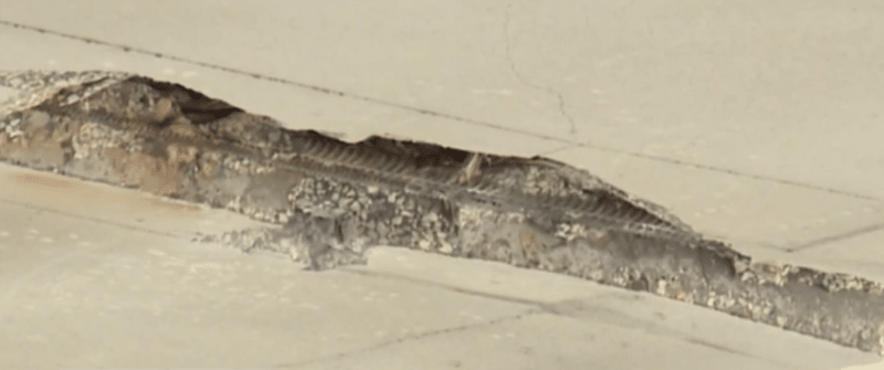
Sounds like they've now found corrosion in both structures
Fo
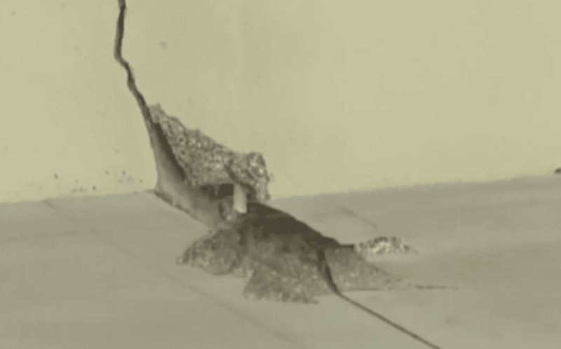
Looks quite similar to corrosion n the tendons found in some older concrete segmental bridges in London a few years ago. Took some major re work to get thos structurally sound again.
Anyone found any drawings of how they tied the box sections together?
Remember - More details = better answers
Also: If you get a response it's polite to respond to it.

Fo

Looks quite similar to corrosion n the tendons found in some older concrete segmental bridges in London a few years ago. Took some major re work to get thos structurally sound again.
Anyone found any drawings of how they tied the box sections together?
Remember - More details = better answers
Also: If you get a response it's polite to respond to it.
I've found several photos online which I believe are of this bridge. (they aren't always labelled) It would seem that the space for bottom tendons is minimal so this bridge is largely a cantilever design. Though the end being discussed looks to be simple supported.LittleInch said:Anyone found any drawings of how they tied the box sections together?
**Disclaimer. Again I'm a rookie in this field so please take my comments with a healthy bit of skepticism.
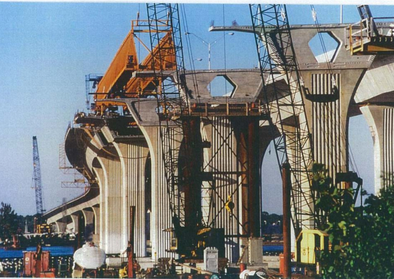
I had a better photograph elsewhere but I can't find it now. There was very few ducts for bottom tendons.
LittleInch
Petroleum
That's an interesting picture. Looks like the sections on the piers are hollow inside to presumably anchor / tension the tendons on both sides. Still looks fairly alarming vertical crack indicating loss of tension.
Section 2.1 of this explains it quite well.
If it is the closure section between two spans then maybe it is the bottom continuity tendons which are problematic / corroding.
Only if they've found issues with the top tendons would the bridge be in serious danger.
Remember - More details = better answers
Also: If you get a response it's polite to respond to it.
- Thread starter
- #16
@
LittleInch said:[/Only if they've found issues with the top tendons would the bridge be in serious danger.]
Any cracked tendon is a serious risk, and the excellent photograph you have posted clearly shows that one (or more) of the bottom (so called continuity) tendons has snapped, as the crack is wider at the bottom, indicating total loss of post tensioning in this area. As the transmission of the shear forces in between the segments relays on the "forced friction" and protrusions matching recesses in the adjoining element, it's a rather big problem. Also, having intact top tendons, and corroded bottom ones, is adding to the positive (LL) moments in the span.
Anyway, any transverse or vertical crack in post-tensioned structure is indication of a very serious problem, and any competent engineer would close such bridge immediately.
LittleInch
Petroleum
I just meant that the bridge wouldn't collapse completely if the top tendons were good but for sure it looks serious.
Remember - More details = better answers
Also: If you get a response it's polite to respond to it.
Remember - More details = better answers
Also: If you get a response it's polite to respond to it.
Perhaps a silly question, but could you design a bridge like this with unbonded tendons, and fill the ducts with grease instead of grout?
I'm sure it would result in larger deflections and anchor forces, but seems like it would be much better from a corrosion perspective. I'm not sure how you replace a corroded tendon that's encased in grout.
I'm sure it would result in larger deflections and anchor forces, but seems like it would be much better from a corrosion perspective. I'm not sure how you replace a corroded tendon that's encased in grout.
- Moderator
- #19
EdStainless
Materials
In FL I wonder what the Cl limit in the mix was?
I just worked a project in a non-coastal area. They are re-building with all duplex SS tension members.
The upgrade is a pittance compared to the project cost (and don't ask about $2million/day in down time).
= = = = = = = = = = = = = = = = = = = =
P.E. Metallurgy, consulting work welcomed
I just worked a project in a non-coastal area. They are re-building with all duplex SS tension members.
The upgrade is a pittance compared to the project cost (and don't ask about $2million/day in down time).
= = = = = = = = = = = = = = = = = = = =
P.E. Metallurgy, consulting work welcomed
- Status
- Not open for further replies.
Similar threads
- Question
- Replies
- 27
- Views
- 28K
- Replies
- 0
- Views
- 3K
- Replies
- 2
- Views
- 8K
- Replies
- 13
- Views
- 13K
- Replies
- 6
- Views
- 3K

