Continue to Site

Eng-Tips is the largest engineering community on the Internet

Intelligent Work Forums for Engineering Professionals

  • Congratulations KootK on being selected by the Eng-Tips community for having the most helpful posts in the forums last week. Way to Go!

THE SAME STEEL AMOUNT IN TENSION AND COMPRESSION OF CONCRETE BEAMS QUESTION 12

Status
Not open for further replies.

eyemeyar

Structural
Oct 16, 2014
14
Hello Everyone. I would like to hear your ideas about doubly reinforced beams that has equal amount of reinforcement in compression and in tension. Is that ideal or no?

Thank you. =)
 
Replies continue below

Recommended for you

Of course we do. I was asking for some deatail and justification for your 2 x (ST stiffness w/o tension stiffening) shortcut as a reasonable upper bound estimate. Does it show up in print somewhere? Is there a graphical relationship that can be pointed to? Does it have a physical meaning that one might be find intuitive? Is it an extension of old school code recommendations like the 6X algorithm? Or do I just have to be smart enough to infer it from first principles somehow?

How come conservatively ignoring tension stiffening, and conservatively allowing for creep and shrinkage by multiplying by 2, needs detailed justification, but conservatively ignoring the concrete altogether can be accepted with no justification at all?

Anyway, the justification is years of comparing results with more detailed calculations, and measured deflections (both research and on real projects).

That said, having checked the steel only results with my approximation and rapt's, they all give about the same order of conservatism. The steel only approach has more variation than the others, but not by as much as I expected.

Here's a summary of my check:
rectangular section, 1000 x 350 thick, 50 cover, equal top and bottom reinforcement:
Light reinforcement: 5 N20, moment = 100 kNm
Medium reinforcement: 10 N20, moment = 200 kNm
Heavy reinforcement: 10 N32, moment = 320 kNm

For each section I calculated the long term curvature, with 5 different methods:
1) Detailed calc, including creep, shrinkage, tension stiffening, loss of tension stiffening to Eurocode 2
2) Sort tem cracked curvature, ignoring tension stiffening x 2 (IDS1)
3) Curvature ignoring tension stiffening and shrinkage, but including creep, x 1.5 (IDS2)
4) Uncracked short term curvature (gross concrete section) x 6 (R
apt)
5) Reinforcement only (KootK)

Here are the results of 2) to 5) as a ratio of 1)

Approx Curve/ Best Estimate
Light Medium Heavy
IDS1 2.6 1.6 1.5
IDS2 2.2 1.4 1.3
Rapt 1.2 1.3 2.4
Kootk 3.0 1.6 1.3


Doug Jenkins
Interactive Design Services
 
IDS said:
but conservatively ignoring the concrete altogether can be accepted with no justification at all?

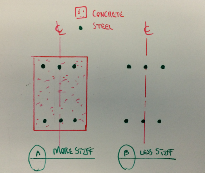
Like all things, it does require justification. I assumed that the justification was so abundantly self evident that elaborating upon it would risk insulting folks. See justifying sketch below. Try not to be insulted.

IDS said:
Anyway, the justification is years of comparing results with more detailed calculations, and measured deflections (both research and on real projects).

You realize that I can't see these things from here, right? I'm happy to take you at your word but, in practice, it's weird for me to use your experience as my justification.

IDS said:
conservatively ignoring tension stiffening, and conservatively allowing for creep and shrinkage by multiplying by 2, needs detailed justification

You and Rapt kinda threw me for loop here. For literally years, we've been having the same, cycling discussion about long term concrete deflections. And the mantra is always the same.

"Span to depth...no good! Simplified north american code deflection checks... no good! Results for lightly reinforced members are not just inaccurate, they're un-conservative! Use our more evolved methods, we have the technology!".

I've been impressed. Truly. I went out and purchased, imported, and digested the texts written by your local heroes. I bought in. When this thread got rolling and you and Rapt said that you knew of better simplified estimating tools, I just assumed that they would be cool new tricks that I was hitherto unaware of.

Surely, you can forgive me for being a little confused to find that 2X this and 6X that are really just the simplified code checks that you normally chastise the commoners for using. I assure you, now that I understand the nature of these algorithms, I require no further justification.

Sometimes I feel like Frodo, chasing you and Rapt around Middle Australia trying to assemble all of the secrets to proper concrete deflection estimation.

IDS said:
Approx Curve/ Best Estimate
Light Medium Heavy
IDS1 2.6 1.6 1.5
IDS2 2.2 1.4 1.3
Rapt 1.2 1.3 2.4
Kootk 3.0 1.6 1.3

Love this. Star for effort. It's interesting to see that the steel only method is as accurate as any of the other approximations for heavily reinforced sections as it is normally heavily, doubly reinforced members where folks will apply the method.

Capture01_wu0o8x.png


I like to debate structural engineering theory -- a lot. If I challenge you on something, know that I'm doing so because I respect your opinion enough to either change it or adopt it.
 
I'm curious if anyone has any thoughts on how far above the neutral axis the compression reinforcement needs to be to be effective for reducing long term deflections?

In the past I'm sure we've all been guilty of saying that the reinforcement at the top of the beam contributes, But probably never checked it as a doubly reinforced section to find out if the compression reinforcement is really effective to take up the concrete stress under creep.

Any thoughts while everyone is on the subject?

Codes just treat it as find area of compression reinforcement and apply blanket effect (and no account of actual depth relative to the neutral axis). In many cases I've seen people take all of the top reinforcement even if it below the neutral axis!
 
Star for KootK on his latest post. I stayed out of this one, having had similar conversations years ago. The fine work of researchers notwithstanding, I still consider the prediction of deflection in actual concrete structures to be a black art rather than anything precise, or even anything accurate. Just my opinion.
 
make sure you have enough stirrups to contain the compression steel
 
And this shows the reason why people should not bandy around their own generalised simplified rules . There are always limitations and those who take on your rules do not understand or extend them past your own limits.

My 6 times rule would be used for relatively lightly loaded "normal" structures such as parking/office or retail with logical L/D's and relatively lightly reinforced. Not something heavily reinforced like the extreme of IDS's examples.

My full deflection calculations would take into account the differences that cause the simplification to not work in some cases.

Also, the difference between a rectangular beam and a T beam is very significant in this. I do not run into many rectangular beams in buildings. They are nearly always T beams.

Kootk can rave on all he likes about more accurate methods that we expouse (not the 6* elastic gestimate), but they have shown to be relatively reliable in practice. Cases where they have been compared to deflections in existing buildings that I have been told about have all been within expected variation due to normal variation in load, material properties etc.

Agent66,
The effect of compression face reinforcement is really too variable to solve by assigning a number. If it is a rectangular beam, it will be more effective than a T beam (the tests for ACI and AS codes on this were based on 600 square rectangular beams initially at least). But then how often do you have a rectangular beam in buildings. They are nearly always T beams.
The effect of shrinkage is normally more significant than creep and it is based on the relative distances of the compression and tension reinforcements from the NA. If they are equal, they cancel and there is no effect. That is possible for an uncracked rectangular section. In any other case, they will not cancel and the more lightly reinforced or the wider the effective flange, the less effective the compression face reinforcement, to the point where the compression face reinforcement might actually be in tension!
For creep, the compression face reinforcement really needs to be in the upper half of the compression zone. Again, very hard to organise in a lightly reinforced T beam or a shallow T beam. Hence our suggestion in earlier posts that compression face reinforcement is much more effective in more heavily reinforced beams and in rectangular beams which have significantly deeper neutral axis because of the lack of a flange.
The only way to allow for all of this is to do the calculations that allow for each of the variables.

 
rapt said:
Kootk can rave on all he likes about more accurate methods that we expouse (not the 6* elastic gestimate), but they have shown to be relatively reliable in practice.

1) I have not once questioned the validity of the accurate methods that you guys espouse. Not. Once.

2) Every last one of these debates has started with you challenging my opinions, not me challenging yours.

I like to debate structural engineering theory -- a lot. If I challenge you on something, know that I'm doing so because I respect your opinion enough to either change it or adopt it.
 
Kootk - the discussion is about quick ways to check upper bound deflection. The question is not whether working on the basis of the reinforcement alone is an upper bound, obviously it is, but then so is span/2, or height of mid-span above ground level. The question is, is it grossly over-conservative. Your sketches suggest it might be, at least for a lightly reinforced section. Looking more closely at the position of the neutral axis, and the associated steel strain it can be seen that there is a limit to the curvature ratio (compared with a fully cracked-section), as seen in the example calculations, but that isn't obvious from the sketch.

In practice, I wouldn't use any of the approximate methods to check deflection. It's just as quick to plug the numbers into a spreadsheet and do a more accurate calculation, but I would do a quick cross-check of neutral axis position and steel strain to make sure the numbers make sense.

On other points raised:
Deflection calculation is a "black art":
I disagree. In my experience, where sections have deflected more than expected, if you do a detailed calculation, including all sources of deflection, the resulting number is close to or greater than the actual deflection. It should be accepted that the "exact" calculation is still an upper bound. In the actual structure the actual maximum moments may be less, the concrete tensile strength may be greater, creep and shrinkage may be less, and differential effects may act to reduce deflections, rather than increase them, so the actual deflection in many members can easily be half or less than the calculated value. That's not important though; it's the maximum deflection that is important, and that can be calculated reasonably accurately, if reasonable upper bound values are used for all the unknowns (including differential temperature, which hardly ever gets mentioned for some reason).

Effectiveness of the compression reinforcement:
Why not just include it in the calculation? Often in slabs it doesn't make much difference, but sometimes it does, so why not include it?

Confinement of compression reinforcement:
I haven't checked the N. American codes, but in the Australian code confinement reinforcement is specifically required for compression reinforcement in beams, if it is required for strength, but there is no requirement if it is for deflection control, or for compression reinforcement in slabs. This makes sense because at service loads spalling will not be a problem, but the compression reinforcement (if it is actually in the compression zone) will have some effect on deflections, albeit usually fairly small.

Finally, for anyone in Sydney on 18th May, please book into the Concrete Institute seminar on Finite Element Analysis, where I will be talking about using computers to understand how structures actually behave (with a focus on deflections), rather than as a tool for design automation.

Doug Jenkins
Interactive Design Services
 
@IDS/rapt: I believe that there is a fundamental logical error in your thinking here that has yet to be acknowledged. You initially came down hard on my suggested approximation because:

1) You had simplified methods as simple as mine.
2) Your methods could do what mine does.
3) Your methods would be more accurate.

I submit that #2 is false. Precisely because of it's conservatism, I believe that my method could serve as a final deflection check whereas your methods, by your own admission (and my concurrence), would only be suitable for ballpark estimates that would need to be later validated more detailed calculations.

So I do not believe it valid to present your rough estimatation methods as being superior to mine in all respects. There is an apples to oranges dimension to this.

Truth be told, the steel only method is something that I probably only tinker with on average about twice annually. Like you guys, I have developed automated tools for most of this stuff. That said, I teach my crew to start with the simplest possible analysis and only proceed to more detailed methods if necessary. The steel only method is a) one tool in the box and b) a tool that works as advertised.

@IDS: any chance that seminar will be recorded or broadcast?

I like to debate structural engineering theory -- a lot. If I challenge you on something, know that I'm doing so because I respect your opinion enough to either change it or adopt it.
 
I use steel only as a concrete check pretty regularly. In heavy industry you see doubly reinforced concrete fairly regularly and sizing is often incredibly conservative. You also see doubly reinforced foundations all over the place.

Normally a check on just the steel either proves that a typical conservative design is fine or verifies that an existing structure is okay. It takes three seconds, no reference materials and can be done with one line of hand math if you want.
 
The deflection specification for cladding on a lot of buildings I am involved in are generally of the order of 6mm-12mm for the supporting concrete element after cladding installation. Gaskets/joints etc are sized based on these limits so accurate estimation of deflection is required. I agree there are some variables which are not fully known at design time and an educated estimate is required, this could lead to the "dark art" association.

I could envisage some applications in heavy industry where strength is the most important design criteria and deflections can be conservatively calculated. With modern computers and spreadsheets i believe it is as quick to run a more sophisticated deflection check as it is to write one line of math.

Ignoring the concrete when calculating the deflection of a concrete element just doesn't logically make sense to me.
 
Kootk - I remain in the papyri camp, but I do concede that the degree of over-conservatism in the steel-only calc is nowhere near as much as I thought it would be.

@IDS: any chance that seminar will be recorded or broadcast?

It's only a 12 hour flight from Canada you know, and when you fly home you arrive before you left :)

But yes, it is possible. We are in the process of putting seminars on the web (for a fee), but where we are with state based ones I don't know.

If you send an e-mail to gmail (dougaj4) I'll send a copy of my presentation, when I've done it.

Doug Jenkins
Interactive Design Services
 
Oh, and the Cement Association of Canada Concrete Design Handbook includes the steel only method.

Table 2.2 in the white pages has design tables for instances using compression steel. It uses a method where you superimpose two cases. If you have two bars of compression steel and three bars of tension steel you look at it as:

Capacity of a beam with one bar of tension steel using concrete as the compression block

PLUS

Capacity of the couple between two bars of tension steel and two bars of compression steel.

When you have equal steel top and bottom, the method implies that you just look at steel.

It's clear that they're doing this in the diagram, but the equations kind of hide it a bit. When you work out the equation back through the various steel percentages and things, though, it's straight up just yield of steel times the moment arm between the tension and compression steel.
 
TLHS,

This is the method I use to verify beams adequacy against moment. The method for the first case uses the difference between tension and compression bars which is 3-2 = 1. If both top & bottom bars are equal, the difference would become zero. If it is zero, then I'll assume compression bars will not yield, since the first case is always initially used to know whether compression bars will yield or not. Hm.. Is there something wrong with my statement? I would love to hear more from you.

Thanks. =)

 
Ignoring the concrete will obviously give a lower bound strength, but I really don't see the point. If you really need a simplified calculation, including the concrete and ignoring the compression steel will also give a lower bound strength, and will usually be less conservative.

But calculating the ultimate moment capacity including the compression steel is pretty easy anyway.

Doug Jenkins
Interactive Design Services
 
There is also a big difference between capacity calculations and deflection calculations!
 
IDS,

I use the method mentioned by TLHS if both compression & tension bars yield. If only the tension bars will theoretically yield, I would use the Moment Capacity contributed by the Concrete block and compression steel bars with yield stress lesser than Fy by summing up moments about the tension bar location. This is the way I know and practice. Do u have other way? =)

Thank you. =)

 
Repeating what IDS said, what's the point. If you have gone to the trouble to determine the strain distribution and neutral axis depth in order to determine if the compression steel yields, why don't you use that information to calculate the capacity using all materials? The concrete is still in compression and providing a compression force in the section and it has an effect on the capacity, so include it.
 
I see some logic in this steel only approach for shortcut deflection check, but no logic at all for capacity. Would anyone design a concrete column, with only the reinforcement considered in the capacity? That would be silly, and it is silly for flexural elements as well.
 
Status
Not open for further replies.

Part and Inventory Search

Sponsor