Eng-Tips is the largest engineering community on the Internet

Intelligent Work Forums for Engineering Professionals

  • Congratulations waross on being selected by the Tek-Tips community for having the most helpful posts in the forums last week. Way to Go!

Thermal Stress Analysis Steps

Status
Not open for further replies.

NoirSheh

Aerospace
Jul 22, 2020
2
0
0
AE
I have done a steady state and transient thermal analysis on a model in Space System Analysi. And obtained .Bun files
Now my goal is to check the shift of one part in the model, due to thermal Stress [thermal deformation]
I have mapped the temperature result into NX 12 Nastran solver Sol 101 linear static. And need to know the setup needed for the structural

Steps I have done:

1.I have loaded the temperature loads from the mapping solution.
2. I have set a contain-> fixed some things (not moving)


The question is
Do I need to define initial temperature for temhe set up?

If temperature result from the thermal analysis At certai. Time.. was distributed between 17C to 25C


Should I specify initial temperature 20 C, in Nastran sol 101?
If I did .. I am assuming NX will take 20C as To (i nitial )

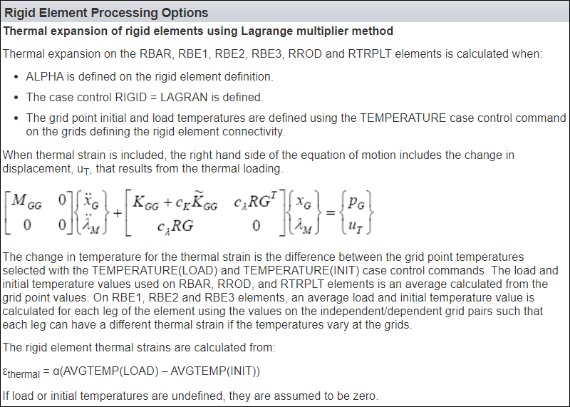
The equation for each node is as follows:
Delta(elongation)=a *Delta Temp* inital length
So delta Temp would be = (20-17,18,19,20.. etc)
Will that give me correct value?

If i did not specify an initial condition what will NX solver count for To?

Also, is there is some tips for this kind of simulation.

I am not familar with NX Nastan .. would really be happy if someone guided me
 
Replies continue below

Recommended for you

Hello!,
This is FEMAP forum, not NX, but we both use Simcenter Nastran solver for finite element analysis.
In FEMAP if the user solve the Thermal problem and have a temperature result then this nodal value can be used as load input.

Heat Transfer Analysis is used to determine the effects Conduction, Convection, and Radiation can have on a structure. Heat Transfer can occur during a Steady-Sate condition or over time with Transient Analysis. Material Properties, Heat Transfer Coefficients, and Heat Flux can be temperature dependent. Flow conditions can be set for Forced Convection, view factor calculations performed for Radiation analysis, as well as many other factors which help determine a system’s behav­ior when thermal conditions are involved.

Running a Heat Transfer Analysis (using either Simcenter Nastran (SOL153) or TMG/THERMAL modules) a temperature will be calculated at each node in the model. Those nodal temperatures will then become the loading condition for a static analysis to determine the thermal stress. In the material properties you need to define clearly the REFERENCE TEMPERATURE value at which THERMAL STRAIN is zero, this way you can use the nodal temperature results as DELTA-T loads or absolute loads.

Best regards,
Blas.

~~~~~~~~~~~~~~~~~~~~~~
Blas Molero Hidalgo
Ingeniero Industrial
Director

IBERISA
48004 BILBAO (SPAIN)
WEB: Blog de FEMAP & NX Nastran:
 
Hello Blas,

Many thanks for you replay and kind explanation, and you are right, I should have posted this in FEM forum.

I have solved my model in NX Space System Thermal for orbiting Satellite [Simulated in vacuum, Thus no convection].This solver is used to account for solar, earth, albedo radiation.

my goal is to make sure the satellite star sensor will not shift due to thermal deformation [Stress]. because a small shift in the sensor can lead to having undesired input.

Therefore, the result obtained from NX Space System Thermal was Already done with no issues I assume. the next step was to calculate the deformation, and NX Space System Thermal don't support such analysis.
I have used the result I got from NX Space System Thermal and mapped it into NX Nastran Sol 101.
another Mechanical engineer have already provided me the Mechanical FEM with RBE3&2. all I had to do is map my thermal solution into his model. therefore the load was already defined.

The steps done is highly similar to this tutorial:

I would like to share the step up. but currently I am out of the office
I hope my writing is clear somehow


I just want to make sure the steps I am following are correct. because The result I obtain dose not meet my requirement . that is why I want to make sure first that my set-up is correct

if you have any tutorials regarding this matter I will be greatful.
 
Hello!,
In Thermal Stress analysis models that include rigid RBE2/RBE3 elements in general this is a serious problem related with the coefficient of thermal expansion (CTE): Both Simcenter Nastran and MSC/MD Nastran support a Coefficient of Thermal Expan­sion (CTE) for Rigid Elements, but you need to activate it, check your NX CAE options.

For most Simcenter Nastran solution sequences which support this functionality, in FEMAP when defining an analysis in the NASTRAN BULK DATA this option must be set to “1..LAGRAN” to have the CTE considered for RBE1, RBE2, and RBE3 elements.

CTE-RBE2_hegcf4.png


cte-rigid-help1_qtufsc.png


In FEMAP, the Rigid element CTE is defined by using the “Coefficient” field in the Thermal Expansion portion of the Define RIGID Element dialog box.
A coefficient of thermal expansion for any Rigid element can either be entered directly into the “Coefficient” field or copied from a defined material using the Material... button in this dialog box.
When using RIGID = LAGRAN in the NASTRAN CASE CONTROL, K6ROT must be defined as non-zero.
The LAGRAN method allows for the thermal expansion of the rigid elements.

rbe2-CTE_zdc162.png


Best regards,
Blas.

~~~~~~~~~~~~~~~~~~~~~~
Blas Molero Hidalgo
Ingeniero Industrial
Director

IBERISA
48004 BILBAO (SPAIN)
WEB: Blog de FEMAP & NX Nastran:
 
Status
Not open for further replies.
Back
Top