Continue to Site

Eng-Tips is the largest engineering community on the Internet

Intelligent Work Forums for Engineering Professionals

  • Congratulations GregLocock on being selected by the Eng-Tips community for having the most helpful posts in the forums last week. Way to Go!

Thickness Build up 2

Status
Not open for further replies.

Amir35

Mechanical
Jun 7, 2016
20
Dear Gentlemen
Here we have a problem ,we are going to weld a 19 mm carbon steel flange hub, with 3 mm inconel 625 overlay ,to a 14 mm Solid inconel pipe, Executing team has presented a plan to build up the pipe with 8 mm inconel and then start welding. On the other hand, we have no free space for using transition piece.
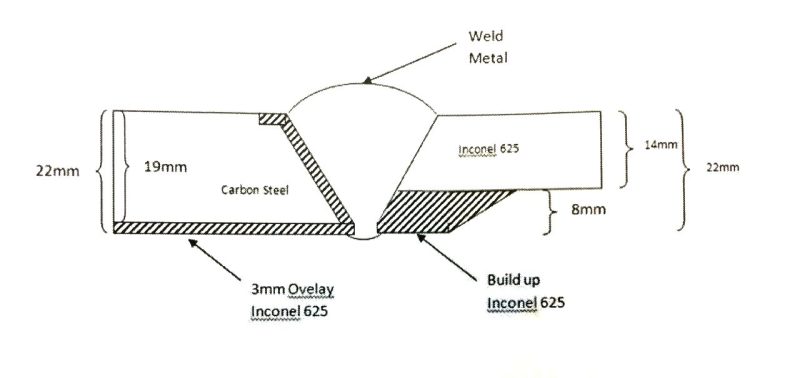
photo487679342050125797_vz902h.jpg

ASME B31.3 Code book recommends using transition piece for this case{Fig 328.3.2(a)}but we have no more room, Then mentioned procedure is not supported by ASME B31.3 Code book,
There are 90 joints like this on each deck and pipe service is sour gas and I don’t feel good about thickness build up .
I appreciate if you let me know your opinion.

Regards

Amir Rokhsativand
Piping Engineer
 
Replies continue below

Recommended for you

How is this "built up"?? Welding? Solid insert?

Looks rather odd, but I guess what you really need to do is do test sections for the welding and then do all the required tensile and bend tests for weld acceptance.

You will also need to look very seriously at fatigue loading and stress concentrations at and around that weld. Dimensions and angles of that ramp need to be shown.

I have a feeling the max deviations are 1/3 t of the thicker pipe, but maybe that relates to other things.

That's my take on it.


Remember - More details = better answers
Also: If you get a response it's polite to respond to it.
 
Thanks for your opinion,The "Build up"phrase is used in ASME SEC VIII DIVISION 1 UW-42,It is Welding Build up,I am agree with you the tests results are needed but before that I need an evidence about this kind of thickness enhancement or someone who had similar experience.
Thanks
 
Amir,
Why not machine a taper on the CS flange to 11 mm and then add 3 mm Inconel overlay to bring you to 14 mm total at the root ?
 
Thanks for joining this thread,Flange is overlaied by inconel in factory and delivered to site prefabricated,also we have design consideration for flange hub.
 
I think this is not a normal approach therefore I don't think you'll see much.

I would start at a minimum axial length of the build up at least the thickest pipe thickness then ramp at 30deg max to your pipe thickness.

Actual tests, especially fatigue, will be required.

Remember - More details = better answers
Also: If you get a response it's polite to respond to it.
 
Amir,
I am lost - I thought the flange was C/S ?

"Thanks for joining this thread,Flange is prefabricated and solid inconel ,also for pressure design consideration"

I am not an engineer but if your piping is rated to 14 mm WT where does "pressure design considerations" come into the equation ?

LI,
Your thoughts on my suggestion"? I thought it was valid but if not would appreciate learning why not.
Cheers,
DD
 
Thanks,I made a correction on the post." Does the hub wall thickness influence on flange rating?"it is the question I had from involved person in the Executing team that supposed to answer by formula,but verbally said "we are not allowed for 8 mm reduction ",I know the important thing is bending stress.
I will be very appreciated if you have any information on this.I am here for your guides
I like the way you think.
 
Dek Dee - Your idea is sound and is the way I would normally expect to do it. It appears that the 19mm bit is a flange hub and is presumably supplied ready coated with Inconel and given that it is a flange hub there may be stress issues.

Why there is no room for even a short Inconel transition piece from 22mm thick to 14mm thick is not clear - for me even a 100mm long transition piece would do much better than this overlay welding idea.

There is no "formula" I am aware of for what the OP is looking at - I guess you could do an FE analysis, but no simple diagram.

Remember - More details = better answers
Also: If you get a response it's polite to respond to it.
 
All Upstream and Downstream spools have been installed and supported,Believe me It's not possible to remove or extend even 1 cm,But thanks for your suggestion.Do you think flange rating is not affected by reducing hub thickness?
Thanks

 
Dear DekDee and LittleInch - Three flange stresses are calculated as follows:
• Longitudinal hub stress:is the bending stress that varies through the hub thickness this stress as essentially a bending stress with
the maximum stress being nearly always at either extremity of the hub.
• Radial stress, consists of two components, the bending stress caused by the radial bending moment and the membrane stress caused by in-plane surface loads on the inside diameter
• Tangential stress the bending stress caused by the circumferential bending moment and the circumferential stress due to membrane stress
caused by in-plane surface loads on the inside diameter

Between these stresses,the tangential stress affected by hub thickness reduction extremely,In attached file you can see by reducing g0(hub thickness from 1.06 in to 0.5 in)St rises rapidly.
 
 http://files.engineering.com/getfile.aspx?folder=9b95f95b-a69b-4501-90ea-e1831809c010&file=g=0.5,1.065.jpg
Status
Not open for further replies.

Part and Inventory Search

Sponsor