Continue to Site

Eng-Tips is the largest engineering community on the Internet

Intelligent Work Forums for Engineering Professionals

  • Congratulations waross on being selected by the Eng-Tips community for having the most helpful posts in the forums last week. Way to Go!

Thickness Correction Factor Kt for Fastener Joints

Status
Not open for further replies.

B767

New member
Jan 13, 2021
19
Good Morning Colleagues,
My question is about thickness correction factor Kt and please correct me if I am wrong - when analyzing bolt or rivet joints, this Kt is the one responsible for the aluminum sheet being joint and Kt take care for the hole diameter mismatch, and when D/T ratio is higher tan 1.0, then kt = 1. Most of the time D/t is higher than 1, otherwise fasteners will not be structural, but here is my question, when D/t is less than 1 where can I get and read data for Kt? Thanks in advance for your thoughts and opinion,
Cheers,
 
Replies continue below

Recommended for you

tell us a little more about your "kt" ... who's analysis are you using ? (generic textbook, company method, ...)
we can help more if we know which text you're using. If a company methodology, best ask there.

in any case a D/t < 1 is a very "odd" arrangement and probably brings other questions to the table ... bolt bending ?

another day in paradise, or is paradise one day closer ?
 
Sorry, I'm a little confused by your question. K_t is generally the nomenclature for a stress concentration factor, whose value is affected by many variables, including material thickness at the detail in question. A thickness correction factor would be something else entirely.

So are you referring to a stress concentration factor or something else? I'm also not sure what you mean by "hole diameter mismatch".

If I had to guess at what you are asking, it seems like maybe you are trying to read a value of K_t from a chart in a stress concentration handbook, but the geometry you have, D/t puts your out of the limits of the chart, and you'd like to know what to do.

Can you provide a sketch of the geometry you have in mind?

Keep em' Flying
//Fight Corrosion!
 
...more details of the design, a 1" wide flange of a unit 0.125" thick is fastened joint to a .071"2024-T3 Alclad sheet using AN3 bolt, and have been asked why material thickness correction factor (Kt) is not included. Never used this material thickness correction factor before for a joint(usually fitting factor 1.15 is the one accepted), using standard Bruhn approach for a combined shear and tension load of a bolt for a margin of safety. Didn't find any reference of it in Bruhn, Flabel, Niu, P.Safarian, etc... nor the NASA TM-2012-217454 Report. Loads are small and the joint is not fatigue critical and is not evaluated for that matter and I don't think this material thickness correction factor is related to a stress concentration factor, but you are right, shouldn't be called Kt, it creates confusion. No winning so far on this, that was the reason was asking for your opinion on this matter, sorry for the late respond, was busy day today,
Cheers,
 
Only things I can think of... possibly whomever is asking the question wants you to account for:

1. Pin bending of the fastener due to offset in centerline of the layers (although this would not generally be a problem for 0.125/0.071 stackup) and/or
2. Additional tension on the layers due to out of plane bending from joint eccentricity due to mid-plane offset of the load path.

Seems like more more detail is required from the person asking you this question.

Keep em' Flying
//Fight Corrosion!
 
Thanks LiftDivergence, that make sense, thanks a lot, will think about it!
 
I'd ask whoever it was who said "what about the thickness correction?" ... "what do you mean ? Show me an analysis method that includes a thickness correction over and above of a fitting factor."

and btw your geometry does not have D/t < 1, you have D/t > 1 (so by your own post, Kt = 1, so NP).

another day in paradise, or is paradise one day closer ?
 
Thanks rb1957, still digging and thinking over it, but if can not find a reliable reference for this factor, will not included, fitting factor 1.15 would be good enough. Thanks for your inputs and thoughts!
 
I don't understand the interest in D/t < 1 if
1) the question is not obvious in the first place (someone has said "what about D/t ?", it which I'd say "what about it ? how do you want me to account for it ? Where's the analysis method ??"), and
2) your geometry has D/t > 1 as per conventional design. (unless you're saying 0.125+0.071 > 0.1875 ? (which it is, but not by anything meaningful).

is this just a random "thought d'jour" ? Someone had me thinking about D/t and everything seems to say "kt = 1 for D/t> 1" ... humm, what if D/t < 1 ?

The issue if D/t < 1 is long thin bolts would have much more significant bolt bending. This really applies to multiple ply lay-ups, with two plies the load shears in on one ply and out the other and as things start to go plastic the load drifts towards the shear plane, minimising bending.

another day in paradise, or is paradise one day closer ?
 
I have requested more clarification what do they mean for that factor, and you said unless they show reliable data and reference so I can be based on, I will not include this factor in the report. But that make sense for me, since you and LiftDivergence were inclined towards bolt bending idea. Initially was thinking if that might be related to a bearing issue and increasing the bearing stresses with the D/t ratio changing, but again no reliable and specific reference for that is on the table
 
Another consideration would be as follows:

The joint strength (ie load capability) of the fastener is actually dictated by many factors. The extreme limits of the strength would be simply plate bearing (Fbru*(t*d)) or each layer, and the shear strength of the fastener shank (Fsu*(pi*r^2)). However, neither of those are generally how an actual joint will fail. The reality is both bearing and shear (and tension) are happening simultaneously and the full bearing or shear strength is almost never realized unless the layers are very thick or thin relative to the diameter.

The actual failure regime is what we call "transitional failure", and if you are familiar with joint strength tables from OEM structural repair manuals you will recognize that term. These tables are general based on empirical data and you can tell pretty easily that the actual strength values are lower than pure fastener shear or layer bearing.

But why is this? Well, most joints have some amount of eccentricity causing the layers to deflect somewhat and also causing minute rotation of the fastener. This manner of deflection causes the fastener to impinge on the layers non-uniformly. This effectively reduces the bearing area to a value lower than simply t*d. The thicker the layers, the worse the reduction of bearing area.

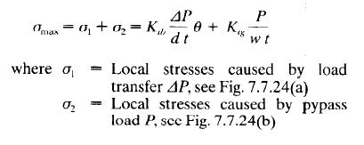
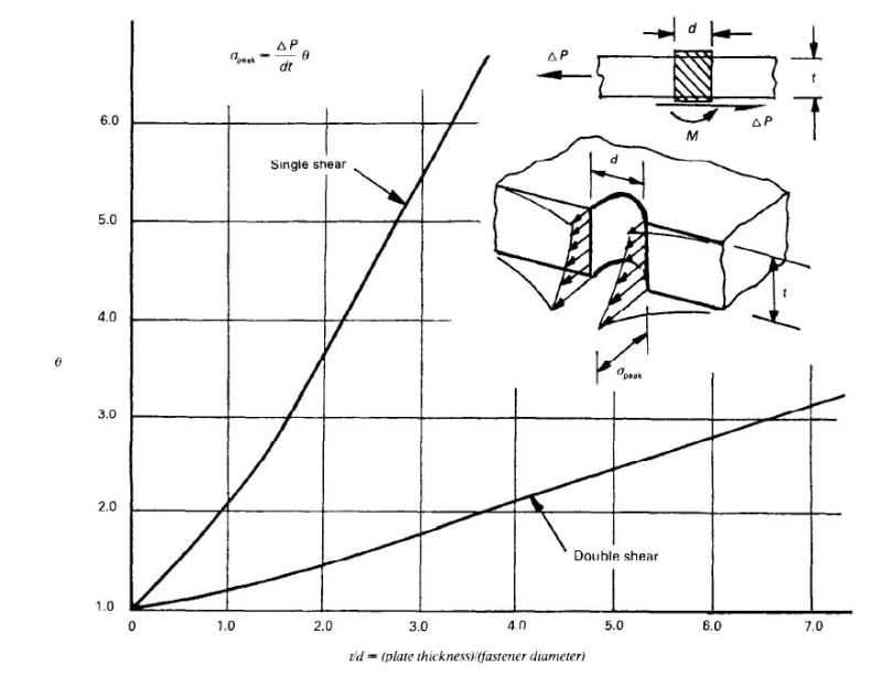
One way you can account for this is by using data associate with the severity factor concept developed by Jarfall. As part of his work, he developed charts for bearing stress distribution factors that accounts for the actual profile of the bearing stress through the layer thickness. This inputs into the bearing stress Kt.

8_yxn595.jpg


9_p1a5af.jpg


10_nakw9u.jpg


Perhaps, if you are writing a joint strength margin based on computed values rather than joint strength tables, the reviewer wants you to account for the bearing stress distribution to approximate the actual transitional joint strength?


Keep em' Flying
//Fight Corrosion!
 
Oo, thanks LiftDivergence, that's a good one, agree on your thoughts, and usually I am referring the joint strength data which is different than actual fastener strength, Boeing have a pretty good data, Northrop and Lockheed and MMPDS as well present these data. So, in Niu's first book is the one pretty close to my problem, he calls it bearing distribution factor which is directly related to the t/d ratio, and his graph (fig 7.7.27) proves it that .071/.190=0.37, so theta = 1.0 I think that's a pretty solid argument. Thanks a lot again LiftDivergence, appreciate it!!!
 
It sounds like it's a very conventional joint. If there is no significant shim then I wouldn't be concerned about bolt bending for static strength.
If fatigue is an issue here, I'd probably opt for a tighter tolerance bolt instead eg nas6203, or a suitable hi lok/hilite/hitigue. You don't have a significant stack-up/diameter ratio, so I wouldn't think eccentricity and bolt bending would be the main fatigue concern.
For thin machined parts with large machining tolerances, analysis to LMC min thickness (or 1.1*min thickness) may be advisable for static strength checks. Perhaps that's what they're getting at?
 
Status
Not open for further replies.

Part and Inventory Search

Sponsor