Continue to Site

Eng-Tips is the largest engineering community on the Internet

Intelligent Work Forums for Engineering Professionals

  • Congratulations cowski on being selected by the Eng-Tips community for having the most helpful posts in the forums last week. Way to Go!

Thin-pipe manifold flow 2

Status
Not open for further replies.

jsenff

Mechanical
Sep 4, 2017
3
Good morning all,

I'm working on a task which is very much not my area of expertise, and I was hoping you might have a few pointers.

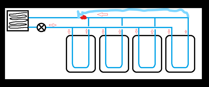
I'm basically creating a rudimentary liquid cooling system, where a pump is supplying coolant through a pipe, which is split off into four liquid tanks, and I'm looking to make the flow through each tee as even as possible.

I've attached a crude mockup for illustration.

The pipes going into the tanks are MDPE SDR11 (material constraints) 25mm OD 20mm ID, and roughly 20-25m in length. The total flow rate from the pump is to be 100 litre/minute with each tank ideally receiving 25 litre/minute.
The distance between the pump and the final tank is ~30ft. I have scope to constrain things further as needed, but at the moment they're quite open ended.

Any advice on where to start would be greatly appreciated, as well as any general design advice. Would I be best using straight tees, or 45° angled tees?

Thanks in advance for your time.
 
 http://files.engineering.com/getfile.aspx?folder=6e2a895b-d1ca-4a7f-ae06-b90c19424999&file=Solution_mockup.png
Replies continue below

Recommended for you

This has been discussed many times. Use Search (top left, under the thread title, between Forum and FAQs) with keywords "flow distribution" and/or "maldistribution". You will get good information.

Good luck,
Latexman

To a ChE, the glass is always full - 1/2 air and 1/2 water.
 
You need to aim for equal resistance/ length as a simple way of doing this, or add in some variable flow resistance. As it stands the first one or two tanks will take most of the flow unless the flow resistance/frictional losses in the tank is very high compared to the losses in the pipe.

At only 30 ft in length I would take the return leg from the right hand end of your diagram for the return leg. This needs a bit more pipe but then you can see that total pipe length of inlet and discharge pipe for each tank is the same.

An alternative is to make the inlet and return pipes very big compared to the tank inlet lines so that the pressure losses in the pipes were very low.

If you really need 25% and not 24 or 23 then you need flow control valves.

Up to you.

Remember - More details = better answers
Also: If you get a response it's polite to respond to it.
 
Gents,

I felt the initial reply would be all I would receive here due to being pointed to previous discussions, so marked it as a "Great Post" and moved on to the research- Apologies for not replying, and thanks for letting me know.

I certainly do not need 25% precisely- some variability in the solution is fine.

>At only 30 ft in length I would take the return leg from the right hand end of your diagram for the return leg. This needs a bit more pipe but then you can see that total pipe length of inlet and discharge pipe for each tank is >the same.

By this do you mean to run the pipe from each tank to the far end, and join with the return there? Makes sense, as you say, to equalise distances.

What would you consider "very big" in this scenario?


Thank you for your time in replying.

Also, I'm (very) new to this forum so didn't know if putting an absolute load of details into the query would come across as "please solve my problem for me", so was intentionally keeping things light to garner direction and general advice.

Cheers.
 
N, what I meant was that on the diagram you provided break the pipe where I've drawn a red bit and connect to the far end of the return header. Then the total length of inlet and return pipe lengths for each tank are similar ( not truly identical) but if you only want to get within 10-15% variance then it's probably good enough. A lot will depend on the relative pressure losses in the pipes compared to the tank cooling system losses.

mod_jmvzo8.png


Very big - say 4 times the diameter of the tank inlet so 100 - 150 mm or so for the inlet and return pipes

Level of detail was about right, but it's never normally too much...

Remember - More details = better answers
Also: If you get a response it's polite to respond to it.
 
Right, yes I see what you're saying now- that makes sense.

Appreciate the input guys/girls, thank you for your time.
 
You could also have the supply and return headers enter and exit between Tanks 2 and 3 to minimize the difference between Tanks 1 and 4.

Good luck,
Latexman

To a ChE, the glass is always full - 1/2 air and 1/2 water.
 
Status
Not open for further replies.

Part and Inventory Search

Sponsor