Continue to Site

Eng-Tips is the largest engineering community on the Internet

Intelligent Work Forums for Engineering Professionals

  • Congratulations waross on being selected by the Eng-Tips community for having the most helpful posts in the forums last week. Way to Go!

Thin Steel Plate Arched Circle Design 1

Status
Not open for further replies.

michmatt

Structural
Sep 28, 2020
5
I am designing a structural steel art structure for exterior application. The structure is a relatively large steel circle (almost a full circle) anchored to a sub-surface concrete foundation. The architectural intent is to create a giant letter "O" with the base cut-off underground. The architect would like 500mm (20") wide x 20mm (3/4") thick steel plate. It will be powder-coated. The maximum span at the two extreme tangents is roughly 20 feet. The height is around 12 feet. It's not a perfect circle. The plate supports self-weight, snow, wind and other loads attributed to exterior art applications, but nothing very high. It is essentially a barrel arch with 500mm (20") length with a modified geometry that strays away from perfect arch geometry.

Can anyone suggest any good technical resources in guidelines or papers? AISC and ASCE have papers on stability and plate walls, but I don't think they apply here. A lot of shell/plate/membrane papers are for thicker concrete art structures which have their own nuances. I intend on analyzing with FEA for strength and serviceability, both in-plane and out-of-plane, but I would like additional focused information on global and local stability and other good tips. Slenderness checks are of importance here because there are areas of compression and tension, but effective lengths from codes and standards are likely not applicable to this type of structure. A detailed guideline or paper would be great.

Thank you.

M.
 
Replies continue below

Recommended for you

BA,

Okay. Everybody sees/approaches a problem differently, no argue about it. But I can assure you that the limiting thickness I came up with wasn't just a lucky guess, it should be able to stood the test.
 
just to start
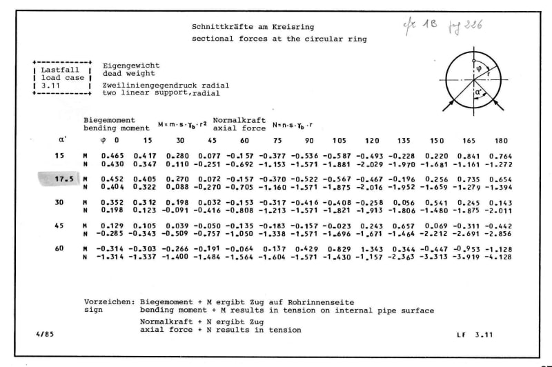
kittel140_dead_weight_fh0fba.jpg
 
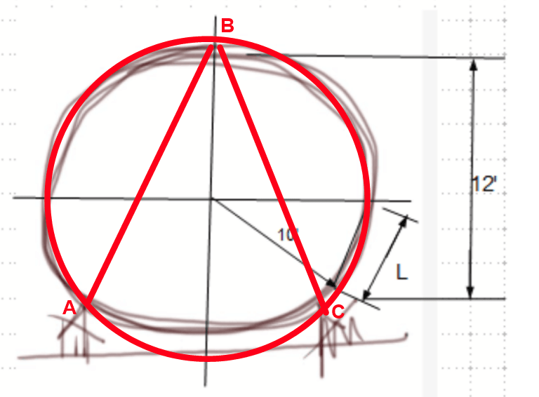
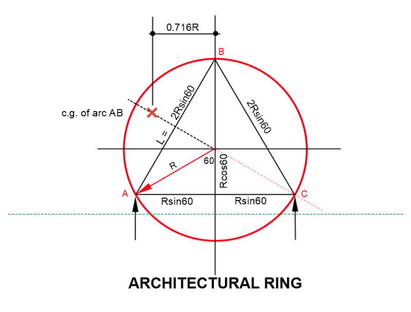
I don't think the circular arch is less critical than the three hinged arch, ABC shown below. So a good starting point for buckling length would be length AB or BC.

image_ix5z1x.png


BA
 
Robyeng,

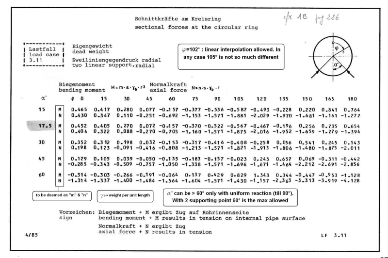
Do you have table for φ = 102°, and ∝' = 78°? In the formulas, what are m, n, s and ϒ[sub]b[/sub] represent?
 
BA,

FYI. Your starting point is, for L = 15.5', t ≅ 7.25" to avoid buckling prior to yield.
 
retired13 said:
BA,

FYI. Your starting point is, for L = 15.5', t ≅ 7.25" to avoid buckling prior to yield.

How did you arrive at that conclusion? And what do you conclude from that?

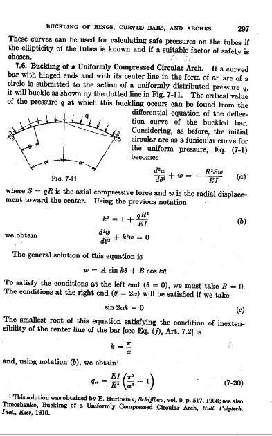
The following is a page from "Theory of Elastic Stability" by Timoshenko and Gere for a two hinged circular arch. It illustrates the buckled shape of a uniformly loaded circular arch. I'm not sure whether it applies when the included angle of the arch exceeds 180[sup]o[/sup], which this one does. If anything, I tend to believe it would be even more critical, but have not gone through the mathematics to check on that.

image_zvhjdx.png


BA
 
BA,

I leave it to you to compare the result from Timoshenko and Gere to mine. I wonder how much the results differ too.
 
Michmatt:
I don’t think that the Arch. is going to get what he wished for, in terms of thinness of the cross section, and that radius of circle if he wishes for that thing to stay standing. I would like that arch to have much more torsional stiffness than a 20” by .75” plate has (++ Edit). Like BA, I’ve not gone through the math, but I suspect that Timoshenko’s solution starts to go crazy before alpha reaches 90°. And, certainly does when the arching action from above starts inducing bending below, when the spring line approaches the horiz. plane through the center of the circle, a full 2’ (plus, plus) above the reaction point. I would probably have someone roll-form a large channel, with the toes pointing in, and then fit a bent pl. inside, to the toes. Alternatively, I’d fab. the thing out of two arched web pls. (arcs, cut out of a 8-10’ piece of pl.), with inner and outer flanges, welded up like a curved box section 3-4” thick by 20” wide. And, a few feet above the horiz. plane through the center of the circle, I’d run the outer flg. on an outward slope (tangent to the circle), down to a base pl.

Due to transport issues, the arch will likely have to be assembled on site. I’d make the webs out of 3 or 4 arced sections and be able to weld them together on site. Then, stagger the flg. butt splices, maybe only a couple lengths or pieces each. Then, the length welding is all done from the outside with fillets btwn. the flgs. and the webs, and to the base pl. And, it’s lifted up into place.

++ Edit: And, some bending strength.
 
If I were starting out blind on this, I'd look at just plain old bending stress.

Think about a huge oblong hoop sitting on the ground (I think the oblong parameter is important). You jump on it. It wants to flatten out, right? I just don't think compression buckling based on some critical stress is going to occur before the sides just fold. I don't think we're going to see much axial force like you'd see in an obtuse arch like in BA's diagram.

Other considerations are base fixity and whether we consider a closed hoop or a chopped hoop. Which I guess could go either way depending on geometry and fixity, again. And if it is already rolled into this exact shape or if it is a little loose and it gets "sprung" into its foundation (such that the outer surface is put into tension).

 
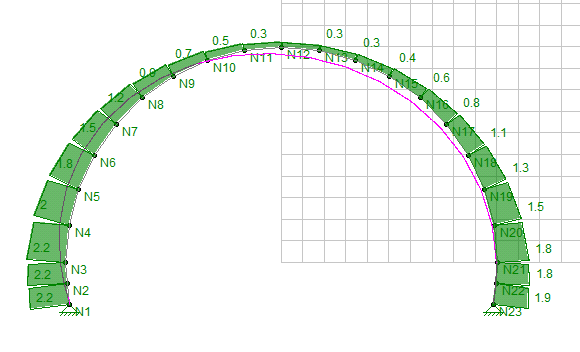
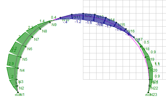
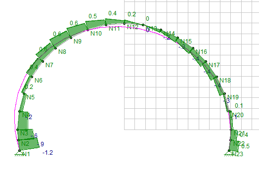
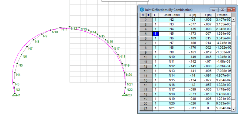
The diagrams below are the results of 3" thick horseshoe shaped metal dome subjected to 50 psf wind load. The design is governed by deflection rather than stress (1" will satisfy stress limits, but too flexible). [ADD: width = 12"]

Axial Force -
image_mmebmj.png


Bending Moment -
image_vrvfzy.png


Shear -
image_cqqzrx.png


Deflection -
image_hpx3oc.png
 

dold said:
30 Sep 20 03:44
If I were starting out blind on this, I'd look at just plain old bending stress.

Think about a huge oblong hoop sitting on the ground (I think the oblong parameter is important). You jump on it. It wants to flatten out, right? I just don't think compression buckling based on some critical stress is going to occur before the sides just fold. I don't think we're going to see much axial force like you'd see in an obtuse arch like in BA's diagram.

Other considerations are base fixity and whether we consider a closed hoop or a chopped hoop. Which I guess could go either way depending on geometry and fixity, again. And if it is already rolled into this exact shape or if it is a little loose and it gets "sprung" into its foundation (such that the outer surface is put into tension).

So would I look at bending stress, but you can't ignore the fact that there will be some compression in the arch. It won't be much axial force because there isn't much load, but there is some and what I was suggesting in the diagram was that the buckling length for the curved arch is approximately the same as distance AB or BC on the diagram.

The proposed member is a plate 20" x 3/4" which has a cross sectional area of 15in[sup]2[/sup], a unit weight of 51#/' and a radius of gyration of 0.2165in. If the diameter is 14'-0" and the space between supports is 12'-0", then AB = 12', so L/r = 144/.2165 = 665, somewhat more than the code would permit for a compression member.

EI = 29e6*20*0.75[sup]3[/sup]/12 = 20,390,000
P[sub]critical[/sub] (Euler) = pi[sup]2[/sup]EI/L[sup]2[/sup] = 9,705#

Total weight of ring = 51*π*14 = 2243#
Total weight of snow = 50*14 = 700# (probably a bit generous, considering the slope)

Reaction at A or C = 2243/3 + 700/2 = 1097#

So it won't fail by buckling, but with an L/r of three times permissible, it had to be checked.
Having done that, I would move on to analyze the arch and I expect it works but leave that to the OP.


BA
 
Thank you everyone for your intelligent insight. You're a smart bunch. Like many projects before this one, it has been put on temporary hold to discuss $$$. We'll have to wait and see if we ever get to play with the hairy math.

M.
 
EDIT: The values highlighted in red were incorrect. The corrected values are in blue.
If the radius is 10' and the supports are 15' apart, then length [highlight #EF2929]AB = 15', L/r = 831 and P[sub]critical[/sub] = 6200#[/highlight] AB = 18.2', L/r = 1008 and P[sub]critical[/sub] = 4211#. Reaction at B and C = 1435#. Probably starting to get a bit limber. How far are we prepared to go?

image_jbfaqu.png


Edit#2: If points A, B and C form an equilateral triangle, then length of AB, L = 15' and the red highlighted figures would apply. But the radius would be 8.66', not 10'.

BA
 
Status
Not open for further replies.

Part and Inventory Search

Sponsor