-
1
- #1
OffshoreWindStructures
Structural
Hello Folks,
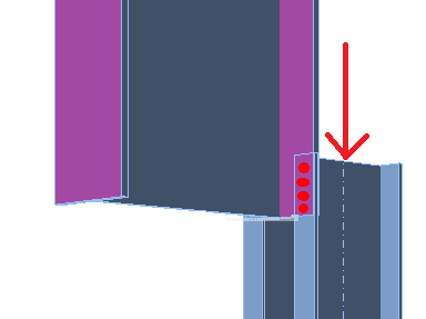
I was wondering what your general thoughts might be on an unusual connection that I've been asked to assess. I've attached an image and can clarify if anything is unclear. The section I am considering is a 20 year old extension to 50 year old structure. The extension consists of a propped beam/truss supporting vertical and horizontal loads.
The internal connections joining the members of the truss extension together are pretty standard but the connections joining the extension to the original steel (purple flanges in image) are unusual as they are an after-thought that have to fit around other elements. The bottom prop connection has an eccentric work point which seems unnecessary to me but is not as unusual as the hanger connection.
The top beam/cantilever has channel extensions to fit around existing objects before meeting the original steel. The hanger connection to the original steel consists of 4 no. bolts with no stiffners, blacking plates or additional support so it's not a full moment connection but I am wondering if it should be considered pinned or partially rigid. The rigidity of the connection will obviously effect how much it will be loaded so I don't think just assuming it as either pin or full moment connection is particularly useful.
I'm also unsure what the critical failure modes might be as there is a lack of guidance on similar connections in any literature I've read. Presumably the lack of similar connections is because it's not a great design, which is clear from first glance. I've been looking a yield line analysis guidance in AISC DG04 as I thought the unstiffened column flange yield line pattern in table 3.4 might be similar but I could be widely off base with that as I don't have significant experience in steel connection design.
Beyond that potential failure mode, I was also wondering if considering the connection as a t-stub in tension might be more valid (such as I looked at eqn J10.1 of AISC 360-10 for local flange bending but I think that might only be suitable for single point loads rather than a series of point loads in a bolt group. There may be an applicable section of AISC 360 that I have missed.
Any thoughts or opinions on failure modes or how best to model the connection are welcome. Thanks in advance.
![[ponder]](/data/assets/smilies/ponder.gif "[ponder] [ponder]")