Eng-Tips is the largest engineering community on the Internet

Intelligent Work Forums for Engineering Professionals

  • Congratulations waross on being selected by the Tek-Tips community for having the most helpful posts in the forums last week. Way to Go!

Thread joint torque setting.

Status
Not open for further replies.

Sach2606

Mechanical
Mar 18, 2021
3
0
0
GB
Hi there
Wondering if someone could help?
We are trying to join the two broken shafts together approx 230mm diameter by screw thread. Thread size is M160 x 6 pitch. Thread length 200mm.Basically male thread on shaft A and female thread on shaft B. The shaft material is S355.

Wondering if anyone knows what would be the tightening torque required?
The shaft is then connected to gearbox which has a output torque of 64000Nm

Any help will be much appreciated

P.S- this is only a temporary fix to get the machine running until the new shaft is made.

 
Replies continue below

Recommended for you

Hi Sach2606

Doesn't sound like a good idea to me even for a temporary fix and depending on which way the shaft turns it either tightens itself or unscrews its self, rather than machine threads wouldn't a coupling be better?
As for maximum torque and if the shaft was trying to unscrew you would need in excess of the 64000Nm torque, that said and I haven't done the maths but someone needs to check that M160 Thread can take 64000Nm but I think the whole idea might be a non starter.

“Do not worry about your problems with mathematics, I assure you mine are far greater.” Albert Einstein
 
The strength of the shaft is roughly proportional to the cube of the diameter. (160/200)^3 is about 0.5 so half the original strength is gone, not including the loss due to the thread.

Temporary might mean not surviving startup loads.

Welders are usually brought in, with the ability to add material to make up for any loss of properties.
 
I think a superior solution would be to make a thick walled sleeve and fit it over the damaged section with interference fit. Is there a limitation on your outside diameter?
 
Some pictures of broken shaft and arrangement with gearbox would be helpful.

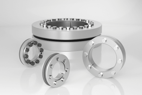
long tubular sleeve with shrink disk locking devices comes to mind -
shrink_disk_h3x1ww.png
 
I've done something similar in the past. What worked, without going thru calculations for your geometry: Fine diamond knurl on the interfaces; Acme threads (metric equivalent); lube the female thread (keep interface dry); torque for all you're worth; then pins.
 
Hi
Thank you all for the comments. Much appreciated.

Coupling or shrink disc cannot be added as the shaft goes through series of collars and bearings before it gets coupled to the gearbox.

The concept to join the two pieces is taken from drill pipe joints.

So the new pieces with male thread will get fastened into the existing piece with female thread and once the mating faces join together to the correct torque setting the two shafts will be pegged with pins at may 3 places 120deg. Then the joint surface will be welded so there is no gaps and then finished turned the bearing journals to required sizes and checked for concentricity.

The shafts turns clockwise so the threads will be right hand so incase the existing shaft jams in the machinery and the new piece carries on turning it will want to screw itself and not unscrew plus the pins will stop the threads getting striped.

The temporary fix is for our customer who has a breakdown.

Also thinking of going for tapered thread instead of parallel like they use on drill pipes.

It will be good to know when we screw the two pieces what torque settings to use.


Hi Sach2606

Well now we know you are pinning it and that two faces of the mating parts are going to butt together I would just put as much torque on it as possible because once the adjoining faces mate it will depend on there relative stiffness and how much they can elastically deform as you tighten the joint and without full details of proposed joint we cannot say what torque to put on the joint. I would make the pins big enough to take the full torque of the gearbox and as I said earlier put as much torque on as possible.
What you haven’t mentioned is whether this shaft is balanced and or what rpm it’s doing, also if you weld what about heat distortion?

“Do not worry about your problems with mathematics, I assure you mine are far greater.” Albert Einstein
 
I believe the purpose of tapered thread on drill pipe is for faster assembly. The taper can be inserted almost fully before the threads engage so it takes fewer rotations to make up the joint. The taper also aligns the connection and centers it before the threads engage preventing damage from banging around.
 
Tapered threads are structurally far stronger than straight threads. With straight threads the wall thickness in the threaded area drops suddenly in the threaded section on both parts (male and female). With tapered threads the wall thickness reduction is almost zero at the start of the thread where the load on the part is maximum, and it tapers to maximum reduction at the end of the part where the load on that part is minimal.
 
Thank you all for the comments. Much appreciated.
@Desertfox - thankyou for the comment. The shaft is running at 425rpm. There isn't lot of weld, the weld is only to seal the joint faces. Also after weld the complete shaft will be clocked and remachined to ensure all diameters are concentric. Also before any machining the shaft will be stress relieved.
 
Status
Not open for further replies.
Back
Top