Continue to Site

Eng-Tips is the largest engineering community on the Internet

Intelligent Work Forums for Engineering Professionals

  • Congratulations KootK on being selected by the Eng-Tips community for having the most helpful posts in the forums last week. Way to Go!

Threaded coupling in flat cover (manway) UG-45 6

Status
Not open for further replies.

Mr.blu

Mechanical
Feb 12, 2022
19
I have seen many posts on the forum about this topic, but I haven't found one that really answers this question.
I will try to be as clear as possible: I have a flat cover that I designed according to UG-34 for a filter, which serves as a manway to change filter elements. If I place a threaded coupling on this cover to function as the equipment vent (it will not have external loads), should it comply with the requirements in UG-45, or would it fall under the 'manway opening'? The idea is to install a 1/2" NPT Class 3000 coupling, but its thickness, while meeting the required thickness + CA and UG-16, does not reach the value in the UG-45 table + CA. It is mainly to understand if a connection placed in a manway is still exempt from what is required in UG-45 when there are no external loads.

What does the code consider within 'manway and access only nozzles' if what I'm saying is incorrect? Is there any part of the code that specifies that UG-45 is aimed at reinforcing connections due to external stresses from piping? Many people express that opinion, but I haven't found it explicitly stated.

Thank you in advance to anyone who can help me interpret this
 
Replies continue below

Recommended for you

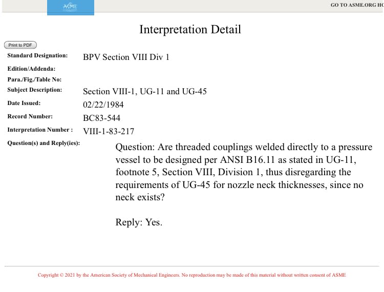
"Interpretation Number : VIII-1-83-217

Question: Are threaded couplings welded directly to a pressure vessel to be designed per ANSI B16.11 as stated in UG-11, footnote 5, Section VIII, Division 1, thus disregarding the requirements of UG-45 for nozzle neck thicknesses, since no neck exists?

Reply: Yes."


-Christine
 
If your threaded couplings thickness does not reach the value in Table UG-45, how will it comply with B16.11 #3000 thickness requirements?
 
I don't know how UG-45 reads currently, however I find it hard to believe it is intended to disallow the use of standard couplings...

Regards

Mike

The problem with sloppy work is that the supply FAR EXCEEDS the demand
 
Thank you for your answers


Christine74

I've seen that clarification before, but I don't quite understand it. Could you explain to me what it means? I understand it as follows, "the standard thickness of the Class 3000 threaded coupling verified for internal pressure is already sufficient, and UG-45 does not apply." Or is there another calculation method in ANSI B16.11?

Both refer to Ansi B16.11. What is the thickness requirement for threaded couplings according to that?

IdanPV
Let me explain my case so you understand: When placed on a flat cover, the required thicknesses tb1 and tb2 are much higher than the "UG-45 + CA (1.6 mm)" table value (2.96 + 1.6 = 4.56 mm) so, when calculating tb, the minimum value is determined by UG-45. The S3000 coupling has a thickness of 3.85 mm, so it complies with UG-16(b) (1.5 + 1.6 = 3.1 mm) and UG-27 (0.10 + 1.6 = 1.71 mm), but not UG-45.

When the connection is on a manway, shouldn't it be excluded?


Again, thank you very much for your responses.
 
Thank you for the clarification.
How did you get 3.85mm?

 
IdanPV

The outer diameter of 1/2" class 3000 couplings is 29 mm, and since the outer diameter of a 1/2" NPT thread needs to be the nominal size of the pipe (21.3 mm), the thickness is 3.85 mm. However, PV Elite gives a slightly lower value (3.62 mm), which also does not comply with UG-45 if included. Do you think I should definitely check UG-45? It seems strange because in that case, no S3000 coupling could be used on a flat cover.

In your opinion, does a coupling welded to a manway that will not even be subjected to external loads require verification according to UG-45?

Thank you
 
david339933
For now that's not an option and i want to understand if it is excluded or not, that is the most important for me right now.
 
Mr.blu said:
The outer diameter of 1/2" class 3000 couplings is 28 mm, and since the outer diameter of a 1/2" NPT thread needs to be the nominal size of the pipe (21.3 mm), the thickness is 3.35 mm.

How is it welded?
 
How is it that your tiny little 1/2" coupling experiences external loading.
Surely, you could use your engineering judgement to class the loading as 'insignificant'.
 
IdanPV

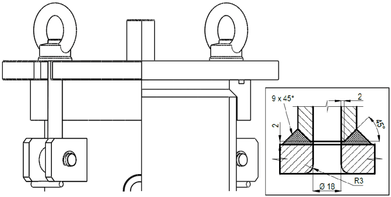
Soldadura_cupla_x8ov3w.png


What is visible is the manway of the filter with the threaded coupling 1/2"NPT welded on the flat cover. The vessel is manufactured with a seamless pipe NPS 8"

I want to see if I understand correctly everything you have been telling me: According to ANSI B16.11, the 1/2" Class 3000 threaded coupling is equivalent to a 1/2" (DN 15) Sch 160 pipe. If I use that thickness and subtract the manufacturing tolerance of 12.5%, do I only need to verify it for internal pressure according to UG-27, and it wouldn't be necessary to comply with UG-45? (Even though I still believe that being in the manway excludes it from the verification)
 
DriveMeNuts

This coupling is simply a vent, it will not be subjected to external loads. Maybe I expressed myself incorrectly before. This is why I believe that UG-45 also does not apply. Is this correct?"
 
Strictly speaking, it needs to comply with UG-45 table, but UG-16 seems acceptable.
But have you taken to the coupling with a Vernier. Often, they are larger than specified.
This is all very bureaucratic.
 
OP,
Are we not talking about 'Opening in Flat Heads and Cover'? Why are we even looking at UG-45?
You have designed the flat head per UG-34. That's absolutely fine. Now if you want to do an opening (vent), simply apply the rules of UG-39, for opening in Flat Heads and Covers.
Why do you want to use UG-45, which is rule for 'Nozzle Neck Thickness'?
ASME B16.11 fittings are acceptable to the Div 1. Make sure that you pick up the correct pressure rating for an equivalent seamless pipe with maximum allowable stress value for the coupling material chosen and the thickness tolerance for the ASME Standard.
You might have to play a bit on the rating to also comply to UG-39 rule on reinforcement area requirement.

GDD
Canada
 
UG-39(a) makes the opening exempt from reinforcement assessment.
Note 1 of Figure UW-16.2 refers to these coupling connections as 'nozzles'.

UW-16(f) Standard Fittings: ASME/ANSI or Manufacturer’s Standard.
UW-16(f)(3)(-a) Fittings not exceeding NPS 3 (DN 80), as shown in Figure UW-16.2, may be attached to vessels that are not subject to rapid fluctuations in pressure by a fillet weld deposited from the outside only without additional reinforcement other than is inherent in the fitting and its attachment to the vessel wall provided all of the following conditions are met
(-1) maximum vessel wall thickness of 3/8 in.(10 mm);
(-6) In lieu of the thickness requirements in UG-45, the minimum wall thickness for fittings shall not be less than that shown in Table UW-16.1 plus the thickness added for corrosion allowance.

So, table UG-45 does apply to your fitting.
Your nozzle is not an access opening.
 
Thank you for your response, to both.

GD2,
GD2 said:
ASME B16.11 fittings are acceptable to the Div 1. Make sure that you pick up the correct pressure rating for an equivalent seamless pipe with maximum allowable stress value for the coupling material chosen and the thickness tolerance for the ASME Standard.
According to that, if I am going to use a 1/2" S3000 threaded coupling, which is equivalent to a 1/2" Sch 160 pipe, I should only make sure that the pipe complies with UG-27 for my design conditions? And then, I just need to check UG-39. I want to make sure I understand what you're telling me.
(Due to the small size of the opening, reinforcement would not be necessary).

DriveMeNuts,
DriveMeNuts said:
(-6) In lieu of the thickness requirements in UG-45, the minimum wall thickness for fittings shall not be less than that shown in Table UW-16.1 plus the thickness added for corrosion allowance.
The threaded coupling 1/2 S3000 meets the requirements of UW-16.1 + CA. It does not meet the value from UG-45 table + CA. I am not sure if I understand correctly, but according to Note (-6), would it be sufficient to comply only with UW-16.1?

General question: What differentiates a manway or access-only type connection from a regular connection, or is that at the discretion of the designer? (I don't think it is, just asking). If the only difference between these connection designations is the presence or absence of external loads, it should be exempt. It is also not in a position where someone could "use it as a step." Despite all the answers I am receiving, I still doubt what the criterion is for defining the type of connection. Is that documented somewhere?

Once again, thank you for your responses; they are helping me understand more.
 
Your coupling nozzle has nothing to do with the manway or access opening clauses.

Your nozzle is a regular nozzle which must comply with Table UG-45.

A much as your nozzle doesn't have loading and may logically be able to use UG-16 thicknesses, the rules don't allow it.
 
OP,
ASME B16.11 fittings are rated against pipe schedule.
In order to establish what rating of the fitting to select, first compute the wall thickness of a straight seamless equivalent pipe material (must be listed in Sec II Part D)for the given design conditions.
Because, I am working in Div1 and pipe is cylindrical, I will use the formula for cylindrical shell in UG-27 to determine t.
t = pressure design thickness.
t required = t + CA
Based on t required, find the nearest pipe wall thickness/schedule from ASME B36.10 (if CS). Consider a typical minus 12.5% under-tolerance.
Once you have this, go to ASME b16.11 Table 8 and corelate the fitting rating. If pipe schedule was Sch 160, the required threaded coupling rating would be 3000#, if XXS 6000#. I would think even a 2000# might work technically, because it's an atmospheric vent.

I don't have the latest Div 1. Can you check the Note 1 from figures UW-16.1 and UW 16.2 to make sure that Couplings are considered as Nozzles. Earlier Editions gave different versions. Nozzles were referenced by specific figure numbers.

GDD
Canada
 
DriveMenuts,

Is this wrong? Or am I misinterpreting it?
B7634CD2-E37D-423D-9E00-23D283FB15A0_zbjibs_obdvke.jpg


GD2,
What do you understand from that interpretation?

(Even when it comes to a manway, they must comply with UG-45, but the formula is different (t_UG-45 = t_a). I'm not saying that compliance is unnecessary; I'm saying that the criteria are different from a common connection)
 
Status
Not open for further replies.

Part and Inventory Search

Sponsor