Eng-Tips is the largest engineering community on the Internet

Intelligent Work Forums for Engineering Professionals

THREADED HOLE WITH COUNTERBORE CALLOUT

Status
Not open for further replies.

CNC PRGRMR 1990

Aerospace
Aug 23, 2021
2
0
0
US
Good Afternoon

I have a question regarding hole callouts

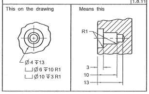
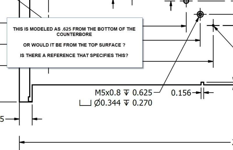
for a threaded hole with a counterbore where does the depth of the thread start

Is it from the top surface or from the bottom surface of the counterbore

THREADED_HOLE_WITH_COUNTERBORE_eo3uhi.jpg


Thanks in advance
 
Replies continue below

Recommended for you

What drawing standard is called for on the drawing? Under ASME Y14.5 they are all measured from the top surface. Not sure about ISO.

 
I would read this as from the CB surface.

This looks like a view on the top surface, showing the CB.
Why would you measure a thread for the top surface ? before or after the CB is machined ? (would you machine the thread, then the CB ? Sure you "could")


another day in paradise, or is paradise one day closer ?
 
From Y14.5:2009

counterbore_vpqybp.png


Also, relative to round holes: "Where the depth dimension is not clear, as from a curved surface, the depth should be dimensioned pictorially."
 
learnt something new today !

so in the case mentioned, the tapped hole is 0.355" deeper than the bottom of the CB

another day in paradise, or is paradise one day closer ?
 
I don't see a dwg standard on the drawing

THREADED_HOLE_WITH_COUNTERBORE2_wy09my.jpg


i thought it was the top surface..... this is a manufacturer of plasma machines..... i thought i remember it being top surface when i was doing aerospace parts...but not sure
 
I'd block out the company name. Per ASME Y14.5, users of the standard are required to specify the specification number and year suffix in order to be applicable. If it isn't there - it's random as to what anything might mean.
 
ok, someone dug up the answer for you, and now you say "but that standard isn't called up". ok, cool, quite correct. but there is a standard for describing the situation.

If you're unsure if the standard applies, why not ask the people who drew the drawing what they meant ?


another day in paradise, or is paradise one day closer ?
 
A few comments related to what has already been stated.

NAS523 standard fastener codes, and my company... for planform views only with standard mechanical fasteners only... have a variety of codes that specify aspects of installation... such as head on the 'N' [near side] or 'F' [far side].

HOWEVER in structural an mechanical installs... with unique criteria such as You have expressed... appropriate dimensioned section views, at standard orientations are shown. Likewise the use of 'line conventions' [solid, broken, phantom, center, etc] prevail... and may be augmented with descriptive flag notes...

NOTE1. USA standard drawing practices and nomenclature prevail [for many of us]... unless otherwise specified. However, for every drawing system [in-country or in a company] there has-to-be definitive documentation that You should reference and work-in-accordance with. Start with ASME Y14.100... for summary of practices... and listing of all related drawing 'sub-practices' [~40 as I recall].

NOTE2. It appears You are converting at 2D CAD drawing to a 3D CAD model-based drawing. Until You become more experienced in the conversion process... and as good practice otherwise... always try to validate all features against a 'real-world' [tangible] part.

PS1. My aircraft has thousands of ancient 'velum' hand-drafted drawings, which represent a real challenge to convert to 3D CAD models for new production parts. Drives designer's crazy. I had one particular designer who trying to model a light-weight sheet-metal flap with 3D CAD precision. They couldn't get the exceptionally slight [~0.20-deg] in/outboard skin contour tapers to match the sheet metal rib-flanges which were all set at 90.00-Deg. It was a challenge getting them to understand thin sheet metal design practices allowed for fit/offsets of +/-0.020-inches and angular miss-matches of +/-2-deg. The standing joke of 'beat[bend]-to-fit, paint-to-match' when right-over-their head.

Regards, Wil Taylor
o Trust - But Verify!
o We believe to be true what we prefer to be true. [Unknown]
o For those who believe, no proof is required; for those who cannot believe, no proof is possible. [variation,Stuart Chase]
o Unfortunately, in science what You 'believe' is irrelevant. ["Orion", Homebuiltairplanes.com forum]
 
Also... [2] minor issues...

1. In the title Block There is a statement 'PROJECTIONS: US" … which implies US drafting practices [in SI units]… which typically points-to ASME Y14.100 [and all sub-practices].

2. Also, wearing my aero-materials 'hat'... "Material: Aluminum 6061" … is an extremely vague description that could lead to MANY problems.

I HOPE Your material specification actually 'reads' more like this [my long-version]...

Material: 6061-T6 or -T651, plate, ASTM B209 or AMS4027 or QQ-A-250/11
Raw Stock Size: XX.xx-ST [as-rolled-thickness... or specify acceptable thickness range 'a.xx-to-b.xx'] X YY.yy-LT [plate-width, minimum] X ZZ.zz-L [plate-length/grain, minimum]

Just saying...

Regards, Wil Taylor
o Trust - But Verify!
o We believe to be true what we prefer to be true. [Unknown]
o For those who believe, no proof is required; for those who cannot believe, no proof is possible. [variation,Stuart Chase]
o Unfortunately, in science what You 'believe' is irrelevant. ["Orion", Homebuiltairplanes.com forum]
 
small point - I think MintJulep's example ia all counterbores, and no threaded holes.

Drawn a year ago and not checked, approved or released yet?
Are you making the parts? Send the drawing back.

Are you tasked with finally checking the drawing?
The resulting "measured from the top" thread engagement of 9 mm/ .355 inch/ 1.8 Diameters is probably OK strength wise, but I would want more with steel fasteners in aluminum.
Regardless I would want someone involved in the design to double check all mating components including fastener length.
Normally a counterbore is added to a thru hole to hide the fastener head.
With a tapped hole at the bottom I'm guessing a spaceer or standoff fits into the c-bore, and a component on top of that, so the 5mm screw is going to be quite long.
The M5 fasteners on the assembly BOM better be based on all the component detail drawings.

The mix of inch diameters and depths and the metric thread is a little curious charge
 
The threaded hole would normally be taken from the bottom of the c/bore, I have never come across a thread depth being specified from a top surface which includes a c/bore.

“Do not worry about your problems with mathematics, I assure you mine are far greater.” Albert Einstein
 
Status
Not open for further replies.
Back
Top