Continue to Site

Eng-Tips is the largest engineering community on the Internet

Intelligent Work Forums for Engineering Professionals

  • Congratulations SSS148 on being selected by the Eng-Tips community for having the most helpful posts in the forums last week. Way to Go!

Three hinge arch - bending moment diagram? 3

Status
Not open for further replies.

dp-17

Structural
Jan 10, 2023
3
I am trying to model a tunnel as a three-hinged arch and I want to find out the bending moments (and shear forces) associated with a three hinge arch with a uniform distributed load on the top. See the below picture.
001-Three_Hinged_Arch_Formulas_UDL_Support_Reactions_Bending_Moments_rxid19.png


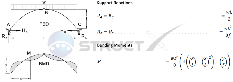
How can I calculate the bending moments? I have used the formula in the picture but I can't get the correct bending moment diagram that it shows in the photo. What am I doing wrong?
 
Replies continue below

Recommended for you

the origin (for x and y) is at A, right?
for x= L/2, y = f; I get M = 0

or is the origin at B ? ... nah ...

I'm surprised that the loading is down, I'd've thought that it would have a radial component ?

"Hoffen wir mal, dass alles gut geht !"
General Paulus, Nov 1942, outside Stalingrad after the launch of Operation Uranus.
 
Does a tunnel (is this a reinforced concrete arch?) actually have a pin at the top? That seems unlikely: it is of no use, difficult and costly to implement and makes the structure statically determinate which reduces redundancy. What about the loading: is it actually a projected vertical load? I would expect rock mass to also push down perpendicularly against the centroidal line of the arch at each section, as rb1957 also suggested - I'm no expert on rock mechanics or tunnel loads, though.
 
IIRC, Roark (or somebody like that) has a formula for max moments in that situation. Would that be sufficient? Or do you need a lot more data than that? If so, i would think you could program a spreadsheet (fairly quickly) with the moment equation (summing moments at short increments, at each cross section) to get values.
 
In answer to the original question:

The shape of the bending moment diagram will depend on the shape of the arch. A parabolic arch subject to a uniform vertical load (and ignoring the self-weight of the arch) will have zero bending moment over the full length. A circular or elliptical arch of the same span and height will be outside the parabolic profile over the full length, and will have a bending moment of the same sign over the full length. A bending diagram of the shape shown would only occur if the arch profile crossed the parabolic profile at about mid height.

In response to comments about the hinge at the crown, it wouldn't make sense for an in-situ concrete structure, but there are plenty of two piece precast concrete buried arches with a hinge at the crown. Lack of redundancy is not a problem because the arch interacts with the soil under load; it is very far from being a determinant structure.

But if this is a buried arch the applied load is nowhere near a uniform vertical load. The vertical load varies across the span, and the horizontal pressure has a huge influence on the bending moments. Also if it is a buried structure interaction between the arch and the fill during backfilling creates a totally different bending effect to applying the load in a single stage, assuming a constant horizontal pressure coefficient.

Doug Jenkins
Interactive Design Services
 
@centondollar - I agree, it is not a very accurate representation of a reinforced concrete arch of a tunnel. What would you suggest is a good way to idealise a tunnel so that the calculations for bending moments and axial loads are feasible to do by using hand calculations?
 
@WARose - ironically I searched up Roark's formulas yesterday for full-circle calculations. Do you think it also has arch formulas on there too?!
 
dp-17 said:
What would you suggest is a good way to idealise a tunnel so that the calculations for bending moments and axial loads are feasible to do by using hand calculations?
Use the actual boundary conditions and loads. As IDS mentioned, the pressure is rarely vertical and uniform for a buried arch, but then again you did not tell us where this structure is situated and how it is to be built, so we cannot speculate further on the loading scheme and boundary conditions.

Ask your supervisor and then create a finite element model. Hand calculations are in my experience not applied for anything remotely complicated (which this arch would qualify as) in structural engineering, since linear FEA involves zero risk of human error in the calculation stage and gives you the same answer as hand calculations as long as you apply a reasonable mesh and material properties, dimension reduction model (e.g., beam), load and boundary conditions as you would in a hand-calculation.

An order of magnitude check for a statically determinate arch can be done easily by hand, and for a statically indeterminate arch, you can use the force method if hand calculations are absolutely necessary, but the solution will probably not be simple if loads act horizontally and perpendicularly to the arch instead of only vertically.
 
@WARose - ironically I searched up Roark's formulas yesterday for full-circle calculations. Do you think it also has arch formulas on there too?!

Yes. At least in mine it does. I have the 6th edition and they have tables for reactions and deformation....don't see anything for moments but (as I said), once you have reactions for a arch....it's a pretty simple thing to come up with moments. Back when I did arches (in my commercial work days) I always thought the challenge was coming up with the reactions.
 
Status
Not open for further replies.

Part and Inventory Search

Sponsor