Rwelch9
Mechanical
- Apr 22, 2020
- 116
Hi guys,
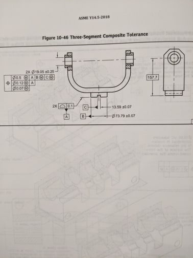
looking at the attached drawing,
Could anyone explain how three-segment composite tolerances work.
Where i fall short is just the general use of the positional symbol .
I have always seen perpendicular or parallel. So just trying to get familiar with using position to control the parallelism or perpendicularity etc.
So the top segment locates the features on the part . ( the 157.7 basic dimension ) in this drawing example to locate the coaxial cylinders to Datum Features B and C would this control the perpendicularity or is there a basic dimension there ( zero ? )
2nd segment = does this ensure the axis of the Ø19.05 is parallel to A.
3rd segment = Does this control the true position between the two Ø19.05
Thanks
Ross

