Navigation
Install the app
How to install the app on iOS
Follow along with the video below to see how to install our site as a web app on your home screen.
Note: This feature may not be available in some browsers.
More options
Style variation
-
Congratulations TugboatEng on being selected by the Eng-Tips community for having the most helpful posts in the forums last week. Way to Go!
You are using an out of date browser. It may not display this or other websites correctly.
You should upgrade or use an alternative browser.
You should upgrade or use an alternative browser.
Three sided excavtion - again
- Thread starter RFreund
- Start date
- Status
- Not open for further replies.
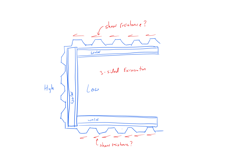
Shear resistance depends on: soil density, vertical pressure (may not be density times height only) affecting horizontal pressure, cohesion and strain. Per the diagram apparently not on the skin resistance of soil on steel. Submergence also, but apparently not submerged.
- Thread starter
- #3
Thanks for the reply.
All good to know but how do we put pencil to paper with that knowledge in mind?
EIT
All good to know but how do we put pencil to paper with that knowledge in mind?
EIT
MTNClimber
Geotechnical
Like OG is saying, there are a lot of variables involved. I'm assuming since there are only three sides that shear resisting walls will retain a slope running parallel to the wall alignment, making things even more tricky. Will the contractor actually cut the slope per your calculations? Probably not. I have an idea of how to go about the calculation but I would end up throwing a decent factor on it to account for variability in assumptions and construction.
At the end of the day I would put more merit into experience. If those shear resisting walls are short enough where you're worrying about shear resistance, maybe you should add rakers connected to a footing. If the excavation is shallow, maybe size the sheet on the left stiff enough where it wouldn't deflect much based on a pure cantilever condition. Based on those previous threads, I'm not sure someone is going to give you a detailed way of calculating the shear resistance.
At the end of the day I would put more merit into experience. If those shear resisting walls are short enough where you're worrying about shear resistance, maybe you should add rakers connected to a footing. If the excavation is shallow, maybe size the sheet on the left stiff enough where it wouldn't deflect much based on a pure cantilever condition. Based on those previous threads, I'm not sure someone is going to give you a detailed way of calculating the shear resistance.
Sheet piles are used to resist lateral soil pressure, not forces parallel to the sheet pile. Admittedly, it does seem like they would have a pretty decent resistance to in-plane loading similar to a shear wall. In your arrangement, you would have 3 sections of cantilevered sheet piling, each resisting the lateral soil pressure, right? Not sure I understand your approach where you end up with some sort of in plane loading on the sheet piles.
My view:
load path: earth pressure to the left wall to the two parallel walls via waler (also acting as strut) to the soil behind the two parallel walls plus a little bit of bearing at the right end sheets.
Soil resistance is similar to a shaft resistance for a pile design, thus unit side resistance estimated with either alfa for clay or beta method for sand, then times the whole (single) face area of the two parallel walls. For working stress method, I would allow for a FOS of 1.5 as a minimum.
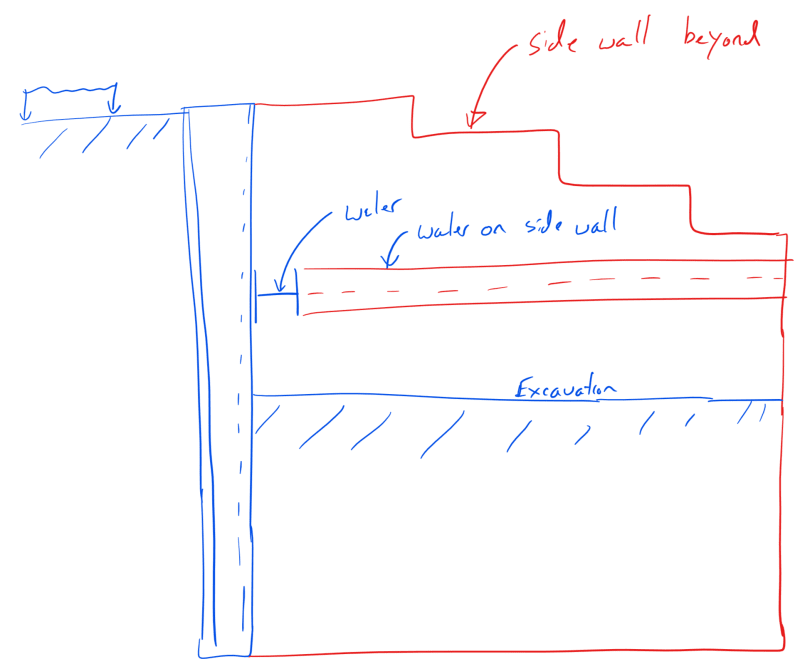
More information on the sketch would be helpful. I assume that the soil behind the 2 parallel walls slopes down from full height at the left end to about nothing at the right end. If so, you will get little (probably insufficient) shear resistance from the parallel walls, especially if these 2 walls deflect toward each other. There isn't a good way to design this as shown. It MAY work if you have enough, reliable, soil cohesion and the soils therefore can stand unsupported as long as needed.
Can you install a single straight wall with a wale and at least two, inclined, raker braces to concrete heel blocks in the approximate locations of the 2 parallel walls? The 2 parallel walls would not be needed if you can safely slope downward from the left wall.
See sketch.
www.PeirceEngineering.com
SlideRuleEra
Structural
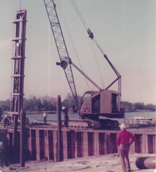
As a 1970's Bridge Contractor, we designed and built a fairly large (but shallow) 3-sided cofferdam to construct a municipal cast-in-place reinforced concrete boat ramp on driven timber piling. Used Engineering Judgment (my father's actually) to rely on the side walls for shear resistance.
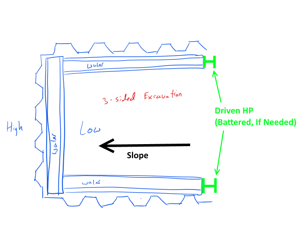
Today, if I had concerns about shear resistance, would avoid the problem by driving an available steel HP or WF at the ends of the side wales. (Contractors doing this type work do have used HP, WF, etc. "on hand".) Wales would be selected with appropriate structural properties for simultaneous bending and axial loading.
![[idea] [idea] [idea]](/data/assets/smilies/idea.gif)
![[r2d2] [r2d2] [r2d2]](/data/assets/smilies/r2d2.gif)
Today, if I had concerns about shear resistance, would avoid the problem by driving an available steel HP or WF at the ends of the side wales. (Contractors doing this type work do have used HP, WF, etc. "on hand".) Wales would be selected with appropriate structural properties for simultaneous bending and axial loading.


![[idea] [idea] [idea]](/data/assets/smilies/idea.gif)
![[r2d2] [r2d2] [r2d2]](/data/assets/smilies/r2d2.gif)
- Thread starter
- #10
Thanks for the additional responses. The soil on the sides does slope down. For arguments sake lets say that the two sides are designed as cantilever sheet piling and if out of plane deflection of the side was a concern we could put in a corner brace or even add a strut between the two side walls.
HenryZAU has the intended load path correct.
HenryZAU - after more research I agree with your method and it seems reasonable. Basically treat the sheet piling as a pile. Conservatively you could treat each sheet as a pile and either use only the embedded portion or some sort of average. Could you explain what you mean by alpha for clay and beta for sand?
PEInc - your assumptions are correct about the geometry. Let's assume we can use a strut at the right end of the waler if needed. To me you would get a lot of shear resistance from the embedded sheet piling. There is a lot of area and you would have to mobilize all the soil behind the wall in order for it to fail due to in-plane shear. I'm curious to know why you think there will be little shear resistance? Also, yes your scheme is very doable, thanks for the suggestion.
SlideRule - I had a couple Geotech guys kinda say the same thing, basically in most cases they would be more concerned with transferring the loads from the waler to the sheeting and preventing the end sheet piles from rotating inward.
Thanks again for all the input!
EIT
HenryZAU has the intended load path correct.
HenryZAU - after more research I agree with your method and it seems reasonable. Basically treat the sheet piling as a pile. Conservatively you could treat each sheet as a pile and either use only the embedded portion or some sort of average. Could you explain what you mean by alpha for clay and beta for sand?
PEInc - your assumptions are correct about the geometry. Let's assume we can use a strut at the right end of the waler if needed. To me you would get a lot of shear resistance from the embedded sheet piling. There is a lot of area and you would have to mobilize all the soil behind the wall in order for it to fail due to in-plane shear. I'm curious to know why you think there will be little shear resistance? Also, yes your scheme is very doable, thanks for the suggestion.
SlideRule - I had a couple Geotech guys kinda say the same thing, basically in most cases they would be more concerned with transferring the loads from the waler to the sheeting and preventing the end sheet piles from rotating inward.
Thanks again for all the input!


EIT
Hi RFreund,
alfa is the reduction factor for estimating pile unit shaft cohesion using undrained shear strength for clay, 0.5 may be taken for your case (alfa times Cu or Su). Similarly beta is the factor for estimating pile unit shaft friction using effective overburden pressure for sand, 0.5-0.8 may be used for your case (beta times effective overburden).
alfa is the reduction factor for estimating pile unit shaft cohesion using undrained shear strength for clay, 0.5 may be taken for your case (alfa times Cu or Su). Similarly beta is the factor for estimating pile unit shaft friction using effective overburden pressure for sand, 0.5-0.8 may be used for your case (beta times effective overburden).
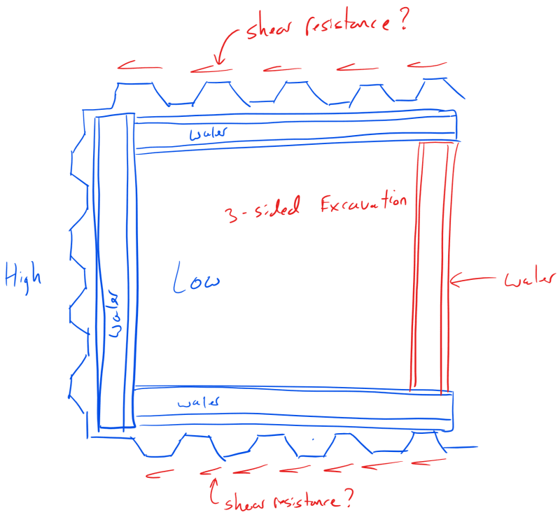
RFreund, the axial load in the two, parallel, SSP walls may not cause the SSP to push in straight lines along the two walls. The 2 SSP walls may push slightly toward each other, away from the retained soil, following the path of least resistance. The extra wale cross brace that you show in your sketch can help keep the axial load in the plane of each wall. As I have said in at least one other similar thread, I have seen 2, long, parallel, SSP walls each buckle in the first SSP double at the end of each parallel wale. How long the parallel walls need to be to dissipate the axial load is, at best, a guess. Be conservative or install the raker braces. In a similar situation, I have also installed a 4th side of braced SSP behind which I had the contractor place some of his excavation spoils in order to minimize or eliminate the unbalanced earth load.
- Thread starter
- #13
PEInc - good point about the buckling, I did read that. Also good catch, it's really not a waler, it is a cross brace. Thanks for the follow up.
EIT
EIT
- Status
- Not open for further replies.
Similar threads
- Replies
- 5
- Views
- 6K
- Replies
- 5
- Views
- 404
- Replies
- 4
- Views
- 207
- Replies
- 1
- Views
- 140
- Replies
- 12
- Views
- 346

