Continue to Site

Eng-Tips is the largest engineering community on the Internet

Intelligent Work Forums for Engineering Professionals

  • Congratulations cowski on being selected by the Eng-Tips community for having the most helpful posts in the forums last week. Way to Go!

Through Holes Steel Structural Column 1

Status
Not open for further replies.

abautis

Mechanical
Jan 27, 2016
4
Hello,

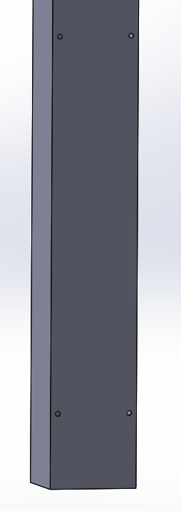
I have concern regarding a hollow steel structural column that has recently been altered. At 4 separate height sections (all of which are separated by about 3 ft from the bottom), 3/8" through holes have been drilled through two given parallel faces. There are two holes at a given cross section, separated at roughly 3.5 inches apart (center to center). The hollow column itself is 7" x 7", with a 1/8" thickness. The column itself is between 70-80 ft tall and helps support the roof. I have included an image to give you an idea of what I am describing. Yes, it would be best if these holes were non-existent.

With an assumed factor of safety of 4 for structural steel construction ( at a given cross section of the column, taking into consideration compression loading (F/A), a new factor of safety was calculated at the new weakest given cross section. This cross section is the point where the entire diameter of each hole (2) has been removed from the given uniform square cross section. This new factor of safety was calculated to be 3.6. We have not included buckling within this calculation, as we do not see buckling being an issue at the hole location given how close to the bottom of the column they are.

I am curious if this is something to be concerned about. We have plans on welding these holes closed later. Thanks!

column_c69dzq.png
 
Replies continue below

Recommended for you

What is your load?

How did you back-calculate a FS of 4.0 for compression? Buckling?

Reducing a factor of safety from 4.0 to 3.6 based on that small a pair of 3/8 dia holes holds only if you are comparing area with the 4 hole against area without the 4x 3/8 holes.

 
An original FS of 4 was assumed from typical FS used in steel structural applications. I have included my source for this assumption. All four holes were considered at a given cross section. This calculation is more of a worst case scenario - I believe that a FS of 4 relates to the weakest joint/section of the structure, certainly not the location of where I am analyzing. In reality, the FS would be much higher locally.

Under this FS=4 assumption, the force was calculated to be around 31,000lbf. Not sure how practical this is - currently not able to get a true weight estimate.

An assumed FS, along with known area and yield stress allowed for back calculation of the weight.

Essentially, the four equations below were used. Thanks!

A=known
A_New=known
P_yield=known
FS=Assumed to be 4
F=back calculate via assumed FS.

P_old=F/A

P_new=F/(A_new)

FS_old=P_yield/P_old

FS_new=P_yield/P_new

I agree with you that this new FS seems quite affected - however my main concern is the overall idea of having these holes in the first place. The particular numbers are important, however I am after a more general consensus about what others think, as I see altering structural supports as NOT good.
 
The holes are of no concern, but a 70-80', thin walled tube section supporting a roof is a big concern. Suggest you need a structural engineer to evaluate this column, unless it is just a trick school problem.
 
Good to know, I may have the thickness wrong. I will investigate further regarding the thickness. Overall my main concern are the holes. Thank you for the input.
 
Thicker doesn't necessarily make it stronger. Check your kl/r ratio. There are limits on this.
 
Always thought the FS was around 1.87, but buckling still has to be considered. You might check the Direct Analysis Method (AISC)for the capacity of column. Be interesting just to see how they pick up a 70 foot plus tube section and keep it straight. Not really sure if the piece can ever be stable at that height.
 
The implication in your post is that this is 70-80 feet unbraced. AISC states that kl/r > 200 should not generally be permitted for compression members. This example has a kl/r of 300. Buckling strength is approximately 5 kips after applying a safety factor of 1.67 (US AISC ASD)
 
Rather than assume a FOS, it is easier to make an educated guess on the applied load. From which you can determine actual FOS. A FOS of 4 is not typical in steel construction, depending on the limit states, FOS of 1.5, 1.67, and 2.0 are the norm. However, that is assuming you're designing to a 1.0 utilized capacity, which is rarely the case, in which case your FOS can be greater than 2.

If you're truly concerned, do a "take off" of what the column is having to support to have an educated guess of the load and run the numbers.

All that being said, if this was a column that was design appropriately to AISC/ASCE codes, I would not worry about the holes.
 
abautis,

How often is this column braced in both directions? A 70' long 7x7 column cannot support anything without buckling. Critical stress is calculated based on the material yield stress and the elastic buckling stress. If your column is braced at very long intervals, you could theoretically be at 100% capacity and your holes just put you over the 100% mark (though this is probably unlikely).

Knowing the unbraced length is needed to evaluate the column capacity, not just the overall length.
 
Great, thank you everyone for the feedback. From what it sounds, we have NO reason to worry about the holes. I will look into the suggested calculation methods outlined. As I previously stated, I will need to reconfirm the thickness of the column, as well as the braced members, and then recalculate. I will be sure to post if recalculated numbers come out unexpectedly.
 
Status
Not open for further replies.

Part and Inventory Search

Sponsor