Slagathor
Mechanical
- Jan 6, 2002
- 129
I am hoping for some experienced feedback on a thrust stand design for a vertical pump application
Axial Load = 22,000# steady state down (there is a change of 0-5 second upthrust, up to 3,000# during start up)
RPM = 510
Radial Loads at each shaft end = minimal. Mainly due to misalignment and drive shaft vibration. No steady state radial loads
Duty cycle = infrequent. 8-12 hours every few months.
Lube = Grease
Cooling - If required will be via an integral fan that pulls air in, routes across bottom of upper bearing housing, and expels out of the frame
The large shaft is a function of the high torque being transmitted - 8,000+ ft-*lb
Design requires spherical roller (SKF 29326E 130mm) to get the required life
Deep groove bearings (SKF 6026 130mm) to take radial load top and bottom.
If shaft grows due to heat, the lower bearing can move down in the housing
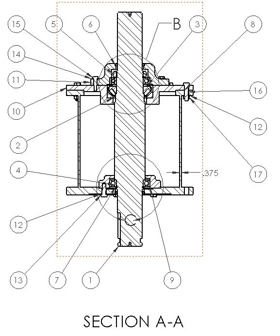
This might be overkill, but here is the preliminary design:

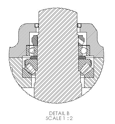
Here is the upper bearing detail. The inner races are locked together, with a spacer, and an SKF nut, locking them to the shaft. The housings are machined so there is a .000-.002" gap above the deep groove to the cap. If there is upthrust, the upper bearing will push against the top cap. While not shown on these details, there will be preload die springs in pockets under the stationary race of the thrust bearing. If it upthrusts, the springs will keep the required load on the thrust bearing (about 4000#). The radial fit on the outer race of the thrust bearing will be loose enough to allow the pre-load springs to work. The radial fit on the upper bearing housing to radial bearing OD will be tight enough to give good radial support, but it can move if upthrust occurs.

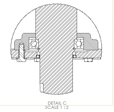
Here is the lower bearing detail. The fit to the housing will again allow the bearing to float axially, so it carries only radial load.

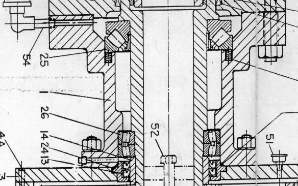
This is sort of a cross between the bearing configuration on a vertical motor, and a large bearing frame end suction pump.
Am I on the right track?
Axial Load = 22,000# steady state down (there is a change of 0-5 second upthrust, up to 3,000# during start up)
RPM = 510
Radial Loads at each shaft end = minimal. Mainly due to misalignment and drive shaft vibration. No steady state radial loads
Duty cycle = infrequent. 8-12 hours every few months.
Lube = Grease
Cooling - If required will be via an integral fan that pulls air in, routes across bottom of upper bearing housing, and expels out of the frame
The large shaft is a function of the high torque being transmitted - 8,000+ ft-*lb
Design requires spherical roller (SKF 29326E 130mm) to get the required life
Deep groove bearings (SKF 6026 130mm) to take radial load top and bottom.
If shaft grows due to heat, the lower bearing can move down in the housing
This might be overkill, but here is the preliminary design:

Here is the upper bearing detail. The inner races are locked together, with a spacer, and an SKF nut, locking them to the shaft. The housings are machined so there is a .000-.002" gap above the deep groove to the cap. If there is upthrust, the upper bearing will push against the top cap. While not shown on these details, there will be preload die springs in pockets under the stationary race of the thrust bearing. If it upthrusts, the springs will keep the required load on the thrust bearing (about 4000#). The radial fit on the outer race of the thrust bearing will be loose enough to allow the pre-load springs to work. The radial fit on the upper bearing housing to radial bearing OD will be tight enough to give good radial support, but it can move if upthrust occurs.

Here is the lower bearing detail. The fit to the housing will again allow the bearing to float axially, so it carries only radial load.

This is sort of a cross between the bearing configuration on a vertical motor, and a large bearing frame end suction pump.
Am I on the right track?

