Eng-Tips is the largest engineering community on the Internet

Intelligent Work Forums for Engineering Professionals

Tie Rod Double Lug Fitting Bushing Holes 3

Status
Not open for further replies.

Kristina Sornikova

Aerospace
Nov 8, 2016
87
0
0
US
Dear experts,

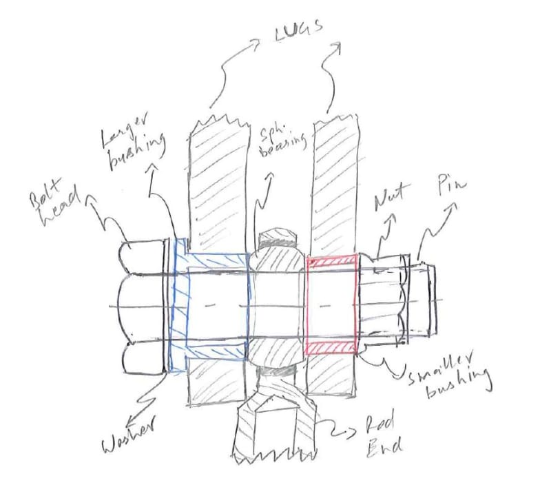
I notice tie rod end double lug fitting has two lugs, one lug has a smaller hole and other a biggger hole for two size bushings, then pin go through center or all bushing, and nut on other side to clamp tie rod end in middle. But why two different sized holes for two different size bushings?
 
Replies continue below

Recommended for you

Usually this is done so that the inner bush on the big side can be full length, allowing the clamp-up to put the bush into compression rather than bend the forkend lugs together.
 
KS... just for clarity... for a dumb-old-guy like me... request You provide an illustration of what You verbally described.

Regards, Wil Taylor

o Trust - But Verify!
o We believe to be true what we prefer to be true. [Unknown]
o For those who believe, no proof is required; for those who cannot believe, no proof is possible. [variation,Stuart Chase]
o Unfortunately, in science what You 'believe' is irrelevant. ["Orion", Homebuiltairplanes.com forum]
 
Hello all its not perfect but something lihe below..
Capture_dxpa1c.jpg
 
There is something terribly wrong with that picture, If you have a tie rod double lug fitting attached to a spherical rod end bearing, the bushings should only clamp on the inner housing ( Ball ) of the spherical bearing, they should also provide clearance for the outer housing of the bearing to move ( Wriggle room). typically this is a detail where two control rods are joined together. This illustration shows none of that.
B.E.

You are judged not by what you know, but by what you can do.
 
@berkshire, right, we see the two bushings clamp on the spherical bearing along pin or bolt axis on faces of spherical bearing, picture is not best, the outer housing is not shown I agree.. but main question is why one sliding bushing body OD is smaller than flanged one?
 
Are you sure there are supposed to be bushings in the holes? That does not make much sense because you already have the spherical bushing. So where is rotation supposed to occur? The double lug with two different hole sizes is usually for use with a shoulder bolt. The small hole is for the threaded part of the bolt and the larger hole is for the body of the bolt. This provides for a very precise tolerance on the clearance between the spherical bushing bushing and the supporting lugs. The bushing must not be tightly clamped between the lugs, but allowed to rotate at the inner bore. The spherical part of the bushing is to allow angular alignment, not rotation.
 
OK... I get it... but oddly complicated design...

I am normally used to the two clevis holes being the same diameter.

The flanged-plain-bushing is usually press-fit [interference-fit] with the lug-hole and the bushing-shank protrudes slightly into the gap between the lugs [ensures clearance with the lug-face]; and...

the plain-bushing is machined for a slight clearance-fit [0.0005] with the lug-hole and is positively longer than lug-thickness to ensure the stack-up cannot crush the lugs together when assembled; and...

the IDs of the bushes allow for a close-tolerance slip-fit of the bolt; and...

the plain bushing is installed 'wet-with grease'... to allow for axial-slip/displacement of the plain bearing; and then...

the stack-up... two bushes, spherical bearing inner-race, bolt, nut and washer(s)... is torqued-tensioned together without binding the lugs together, since all binding occurs against the flanged bushing end/hat/lug and the inner-race of the spherical bearing.

DANG... RPstress already said this in far simpler terms.

NOTE.

This design methodology works well for complex parts in flight control systems with anti-friction bearings, too.

Regards, Wil Taylor

o Trust - But Verify!
o We believe to be true what we prefer to be true. [Unknown]
o For those who believe, no proof is required; for those who cannot believe, no proof is possible. [variation,Stuart Chase]
o Unfortunately, in science what You 'believe' is irrelevant. ["Orion", Homebuiltairplanes.com forum]
 
Right WKtaylor, all of that I clear now, but as I say the figure is not the best, bushings are protrude inside to clear bearing, etc. all good.

But still my question not answer... why OD of flange bushing > OD of slide in bushing?
 
It would appear that somebody has designed this to make life easier for the mechanic, The most common configuration for this type of fitting is to place a small OD washer between the inside faces of the hemispherical bearing and the inside faces of the lug/clevis, on a nominal bolt clearance hole, then insert a Plain bolt through the lug/clevis and tighten down. Then depending upon the design philosophy of the manufacturer the lug is left finger tight with a castellated nut and cotter pin , or it is clamped tight forcing the Uniball joint to rotate upon movement . The two bushings eliminate the need for the washers. I would however like to see a washer under the nut on the red side, without it the assembly would be free to float until the outer housing contacts the side of the lug.

You are judged not by what you know, but by what you can do.
 
The installation shown is similar to what ARP 5770 specifies (figure 68), except the blue hat bushing should be installed with the flange on the inner face of the clevis lug.
 
I find nothing odd about this design. Every feature in the lugs has a purpose.
In fact I plan to use one like it on an upcoming project.
The only feature I missed was the differential OD, which makes sense if you can't install the through-bushing from the right side, for some reason. It can pass freely through the left-hand hole to be pressed into the other lug. If I had 1000 of these to assemble, I'd be happy to not have to flip the lug over in the fixture, because that would save a few minute on each assembly.

No one believes the theory except the one who developed it. Everyone believes the experiment except the one who ran it.
STF
 
SparWeb... Also the joint is complicated from another perspective... especially where relatively small clevis joints are concerned.

Two clevis lug holes [bushed or not-bushed] would be just fine as the 'same hole diameter' for a slight clearance fit... IF the thru Bolt was a shoulder-bolt that had a grip-length slightly longer than the cross-the-outside-dimension of the clevis [and of course a washer and castellated nut and cotter-pin]. Typical shoulder Bolts...

NAS1160 BOLT, SHOULDER, HEX HEAD, CLOSE TOLERANCE CRES-A286
NAS1297 BOLT, SHOULDER - HEXAGON HEAD
NAS1298 SCREW - BRAZIER HEAD, SHOULDER
NAS1299 SCREW - 100' FLAT HEAD, SHOULDER

Plus castellated nut and a thin steel/CRES washer

Regards, Wil Taylor

o Trust - But Verify!
o We believe to be true what we prefer to be true. [Unknown]
o For those who believe, no proof is required; for those who cannot believe, no proof is possible. [variation,Stuart Chase]
o Unfortunately, in science what You 'believe' is irrelevant. ["Orion", Homebuiltairplanes.com forum]
 
Great ideas WKTaylor, and I do appreciate the value in clamping up on the shoulder. The NAS hardware you linked is not quite big enough for the future application I was referring to, though I have seen them used successfully as you describe. Door hinges, etc.
The application in my case will have complex geometry through with the fastenings must be made. No hope of getting the "jesus bolts" to align in a nice rectangular pattern. Interfaces need fittings that allow for misalignment during installation, yet remain very stiff when all the bolts are done up. Sorry if that sounds cryptic - trying not to hijack this thread.


No one believes the theory except the one who developed it. Everyone believes the experiment except the one who ran it.
STF
 
I think the key design feature is there is a clearance gap (or should be IMHO) between the clevis lug and the rod end, so that the bolt is clamping the bushings and not clamping the clevis.

Another thought is what is the impact of clamping the clevis ? what are the working loads/stresses like ? (If low then you can get away with clamping the clevis.)

Does the joint articulate ? (then I wouldn't clamp the clevis)

Does it really matter to the joint if assembled the wrong wey ? (ie if different diameters are "only" to prevent misassembly, why is this critical ?)

Sometimes "fussy" design is required, but sometimes it's done 'cause that's what the designer knew.

another day in paradise, or is paradise one day closer ?
 
OK I get it... sorta...

I have a current situation where a stock shoulder bolt ['company-spec'] is altered for a special application [shortened threads for clearance] on a drawing. These 'company-spec' bolts do not have length limitations of the NAS bolts [I cited]. These bolts are used in engine mount connections in close-spacing to honeycomb fairings.

I nave been seriously contemplating making these 'drawing' bolts by altering [making from] stock NAS6312U42 or NAS6712U42 [or longer] bolts [procurement spec = NAS4003]. This is a 3/4-Dia bolt that is already certified and on-the-shelf.

In this case I would trim the shank/threads-off to the length required [to start]; and grind the end down for threads [0.6250-18UNJF-18A]; and then have the threads installed by cold-rolling and the excess thread-tips ground down [to max allowed diameter]; then have the new threads NDI'ed; and then have the thread transition area glass-bead blasted for clean-up; then have a cotter-pin-hole drilled thru the threads as required; then static test at least one to ensure clean ductile break at a reasonable strength.

Perhaps You might want to consider making shoulder bolts. IF there is no significant tensile load in the bolt, then machine the each-one.

NOTE. I've kicked-around a simpler way to do this... groove the thread transition area and then cold-roll-work the groove... then install a 'snap-ring' and then install a thin CRES shear and nut to a low/snug torque against the snap-ring.

Regards, Wil Taylor

o Trust - But Verify!
o We believe to be true what we prefer to be true. [Unknown]
o For those who believe, no proof is required; for those who cannot believe, no proof is possible. [variation,Stuart Chase]
o Unfortunately, in science what You 'believe' is irrelevant. ["Orion", Homebuiltairplanes.com forum]
 
Wil,
I guess I just don't have the guts to start making bolts. That said, I've made barrel-nuts before, as in personally at the lathe/mill for a day. In that case, cut threads in the nut, but hardly any tension in the joint. For your project, have you also found qualified surface finishing vendors? I'm just thinking of a very long chain of processes needed to make the bolt well enough to minimize the "pucker factor". Turn down end, thread roll, grinder touch-up, (shaker table?), NDI, blast, drill thru thread, (plating?) and pack it up to go. That bolt goes from expensive to priceless, if it's a small batch. That would be a gutsy move, even for me. [smile]

My current inspiration is Boeing BDM 1520. That is full of illustrated fitting arrangements like a designer's catalog. I'm in the "self-aligning" and "Clamping" and "fusible" category so that the transverse load can be applied to both lugs of the fork, yet the equipment must break away in case of a gear-up landing.


No one believes the theory except the one who developed it. Everyone believes the experiment except the one who ran it.
STF
 
SparWeb... Your case, large dia/long fasteners for clevis joints...

Fud-4-Thot...

Ever considered using bolt [drilled threads] with grip-length exceeding clevis width... then fastening with a combination of thin solid washer + wave-spring or Belleville washer + thin solid washer + castellated Nut and cotter pin? Specify a torque on the castellated nut that is 'just enough' to get noticeable/light compression of the spring-washer before cotter-pinning.

Regards, Wil Taylor

o Trust - But Verify!
o We believe to be true what we prefer to be true. [Unknown]
o For those who believe, no proof is required; for those who cannot believe, no proof is possible. [variation,Stuart Chase]
o Unfortunately, in science what You 'believe' is irrelevant. ["Orion", Homebuiltairplanes.com forum]
 
Yes, thank you. I will think about the Belleville washer idea.
The bolts in the joint will probably be removed ~10 times in the life of the mission, ie, once per year to afford access for inspection.
Considering that, I will have to expect the bushings, washers and bolts to be replaced at some point. Thankfully, Bellevilles aren't so rare.
Going back to BDM1520, the reasons to avoid clamped lug fittings are made plain, and your suggestions amplify my interest in the alternatives.


No one believes the theory except the one who developed it. Everyone believes the experiment except the one who ran it.
STF
 
Status
Not open for further replies.
Back
Top