Continue to Site

Eng-Tips is the largest engineering community on the Internet

Intelligent Work Forums for Engineering Professionals

  • Congratulations KootK on being selected by the Eng-Tips community for having the most helpful posts in the forums last week. Way to Go!

Tilting pad journal bearing design

Hesam267

Industrial
Jan 28, 2016
29
Hello. Friends, please help me in the design of the tilting pad radial bearing.
I did not find any useful information about the curvature of the back of the pad in these bearings. Apparently, this curve is called backland. What are the design principles of this curve based on?
 
Replies continue below

Recommended for you

I did not find any useful information about the curvature of the back of the pad in these bearings
I would think the curvature of the front of the pad (facing the journal) is critical but the curvature of the back seems relatively unimportant since it contacts nothing except at the small area of the pivot support (rocker). Are you asking about that rocker geometry?
 
Hi. The front side of pads (near shaft) is really important. But it is unlikely that the back part of the pads is not important, for these reasons:
Suppose the curvature of the back of the pad is the same as the inner curvature of the housing, in this case the pads do not perform any tilting. Now suppose the curvature of the pads is much less than the curvature of the housing, in this case the pads will tilt with the least force.
 
There are many options for the pivot on the back of the pad. The most common would be a button design with the button being a much smaller curvature than the bore it rests on. This is essentially a point contact which allows the pad to pivot in any direction. That point contact will tend to fret or wear, increasing the bearing clearance. Other bearings use a key on the back that creates a line contact. This design only allows pivot in one direction so the alignment of the bearing bores becomes more critical. The least common design is a ball and socket or spherical pivot. This allows pivot in any direction, but provides much greater surface area to avoid pivot wear. The pivot is usually in the center of the pad. Offset pivots can be used to make the gap between the pad and shaft more or less tapered.

Johnny Pellin
 
This is a very similar application to that of a 2 stroke engine wrist pin. Perhaps there is more information for that subject? Single direction load with an oscillating movement. Very hard to lubricate.
 
Suppose the curvature of the back of the pad is the same as the inner curvature of the housing, in this case the pads do not perform any tilting.
That's different than what I was envisioning in my last response. I was envisioning the type of pad described by JJPellin which has a single pivot point in the back. That's an older style that I am familiar with. I do believe it will have the limitation that the pivot either needs to be in the center of the pad (simple design where pad can be installed in two orientations and direction of machine rotation can also be reversed) or else if the pivot is not in the center of the pad arc then the pad needs to be installed in a certain orientation and rotation is not reversible.

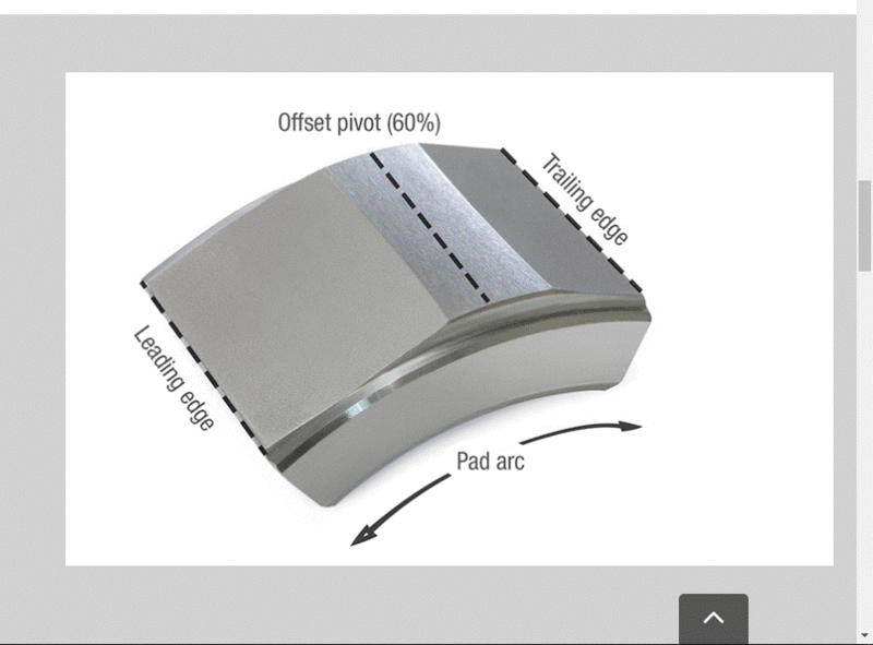
I see on the internet there are newer styles like the one shown below with a flat strip along the center of the back of the pad. It is easy to imagine that this type will have an offset-from-center pivot point on each side of centerline depending on the direction of rotation (so it eliminates the limitation described above). The design of the pad will presumably include the offset-from-center angle as an important variable, and that angle can be inferred from the pad geometry (including the backside) and the housing. That's just my thoughts fwiw, I'm sure there's a lot more to it. I dont' have any links.
pad-flatspotOnBack_lghfkt.gif
 
The back curvature is designed to ensure that the pad can tilt freely and adjust dynamically to the rotor's motion, helping to maintain stability and avoid excessive contact or wear. This curvature also ensures that the pad distributes the load evenly across the crossed roller bearing surface, improving the bearing’s performance under various load conditions.
 

Part and Inventory Search

Sponsor