Continue to Site

Eng-Tips is the largest engineering community on the Internet

Intelligent Work Forums for Engineering Professionals

  • Congratulations KootK on being selected by the Eng-Tips community for having the most helpful posts in the forums last week. Way to Go!

Timber frame? cantilevered column? 1

Status
Not open for further replies.

AaronMcD

Structural
Aug 20, 2010
273
I'm bidding a horse arena, and the owner wants to use wood trusses. In order to keep the sides open, I'm trying to find any requirements for timber lateral resisting systems (SDC D). There is a system called "timber frames" under "cantilevered columns", but I can find no information anywhere as to what this means.

Is it any framed timber, such as knee braces? Or is it only for embedded columns and pin connections?

Thanks

 
Replies continue below

Recommended for you

I have looked into this myself and still can't figure out what "timber frames" entails. Also you might not even be able to use it in SDC D-F (correct me if I'm wrong) based on that table.

I assume it's just the regular timber frame with kickers (you call it knee braces) that you use for open patio covers. Technically you can't use it for certain SDCs but no plan checker has ever cared since they are used everywhere lol

As for cantilever wood column I have never used embedded columns however Simpson Strongtie has a fixed-base connection you can use. Albeit the capacity is very low and again the SDC limitation still applies.
 
Check out this from the Timber Frame Engineering Council: Link

Do a word search for "Seismic" and they give R, C[sub]D[/sub], and Omega. Keep going through it and you get to the commentary where they explain how they came up with the values.
 
AaronMcD :
PhamENG’s link looks like a good ref. on real Timber Framing, I think I’ve seen that before, but I don’t think that is what the OP’er. was talking about when he said “There is a system called "timber frames" under "cantilevered columns", but I can find no information anywhere as to what this means.”

In the case of a large horse arena, I think they are talking about long span 2x wood trusses, with pressed steel truss pls. (TPI), etc. The columns are fairly large, and maybe spaced a 6 or 8', so that pre-cut 2x purlins drop into jst. hangers on the trusses. There may be double (side by side, sistered) trusses fitted into a vert. col. notch, or there may be 2 trusses, each bearing on the 2 outer side plies of the column. If the truss has a heel depth of 2 or 3', a moment connection can start be made at the top of the col., maybe with shear pls. dapped into the col. and into the inside of the trusses, and then through bolts. Knee braces probably exist btwn. the col. and the first panel point on the trusses. Obviously, the truss design and the col. design and found. design must take this all into account. This starts to be a rigid frame, but may still not be enough for a large bldg. like this, and to meet today’s bldg. codes. There are several laminated wood outfits which make laminated 2x col. members of various sizes and lengths, with the bot. 6' or so preservative treated, for pole barn bldgs. Two being: Rigidply Rafters, Inc., and Gruen-Weld Classic, I think. This will end up being a classy, properly braced, engineered pole barn.
 
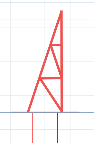
How about something like this?

Capture_ttt53y.png


BA
 

When you look Clause 11.2 DEFINITIONS , You will see ( copy and paste of the definition )

CANTILEVERED COLUMN SYSTEM: A seismic forceresisting system in which lateral forces are resisted entirely by columns acting as cantilevers from the base

That is, the column is fixed at the bottom and pin at the top.

When you look 12.2.5.2 Cantilever Column Systems there are two limitations,

- The required axial strength of individual cantilever column elements, considering only the load combinations that
include seismic load effects, shall not exceed 15% of the available axial strength...

- Foundation and other elements used to provide overturning resistance at the base of cantilever column elements shall be
designed to resist the seismic load effects, including overstrength of Section...
 
@ HTURKAK

That doesn't answer his question though. Especially the vague "timber frames" system
 
I think it should all be taken in context. I have ASCE 7-10 on my desk, I imagine 7-16 and -22 are the same but that should be verified if important.

12.2 STRUCTURAL SYSTEM SELECTION
12.2.1 Selection and Limitations. "...Siesmic force-resisting systems not contained in table 12.2-1 are permitted provided analytical and test data are submitted to the authority having jurisdiction for approval that establish their dynamic characteristics and demonstrate their lateral force resistance and energy dissipation capacity to be equivalent to the structural systems listed in table 12.2-1 for equivalent values of response modificaiton coefficient, R; overstrength factor, Omega[sub]0[/sub]; and deflection amplification factor, C[sub]d[/sub]."

C12.2 STRUCTURAL SYSTEM SELECTION
C12.2.1 Selection and Limitations. "...FEMA P-695 (2009b) has been developed with the purpose of establishing and documenting a methodology for quantifying seismic force-resisting system performance and response parameters for use in seismic design. While R is a key parameter being addressed, related design parameters such as the over strength factor, Omega[sub]0[/sub], and the deflection amplification factor, C[sub]d[/sub], also are addressed.

Table 12.2-1: only one timber frame is listed, and that is the timber frame located in the cantilevered column section. Timber frames consisting of cantilevered columns are very common - as dhengr pointed out, they are commonly referred to as pole barns. Timber piles are driven (or set in augered holes) deep enough to develop base fixity and it is from there that the frame derives its stability. Cantilevered column timber frame.

I think the absence of any other timber frame isn't that it's disallowed outright, or that the cantilevered column values should be used for all of them (though an R of 1.5 would likely be conservative, the overstrength and deflection amplification values may not give sufficiently reliable connections and drift estimates relative to the proportions of the frame). I think it's just a relatively uncommon framing system with too many variables for ASCE to put it in the table.

So if you're going to do a pole barn, then use the cantilevered column section. If you're not, and you're going to use knee braces, get buy in from the AHJ and use the values laid out in the TFEC document I linked above (which the commentary states is based on FEMA P-695). If you're doing something else, you'll need to find somebody who has assessed the framing arrangement per P-695 or a comparable method to give you the necessary values to evaluate the seismic resistance.
 
Thanks all.

I hadn't heard of pole barns. I guess that might require very large columns, but the simplicity is nice.
I have heard from the architect that a lateral system will be ok in select bays, but I may look into knee braces as well. I just like the idea of knee braces better than bringing in structural steel or adding walls.

Do you (phamENG and anyone else with an opinion) think it is reasonable to apply the same seismic coefficients to moderns joinery vs. the traditional joinery discussed in the timber frame engineering council link, provided I get approval from the AHJ?

 
I think you probably could. I'd take a look at the reference documents and see just what they built and tested and do a comparison with your proposed connections. See how different they are and figure out how you think their behavior will be different. After all, most of the concern is in the behavior of the frame. So long as the connections provide the same basic restraint, you should be good to go. And more modern connections may make it easier to meet the test derived over strength in the commentary.
 
I've used the TFEC values for all my timber frame projects.
 
So I got a proposal signed for schematic design.

3 more things I'm looking into. If any of y'all feel like popping in with insight it would be appreciated and maybe save me some research time. :)

1) Foundation ties. I recall buildings require all foundations tied together in 2 directions. Anyone know the reference for this? Maybe IBC foundation chapter? 100 ft long ties are probably expensive, so limiting those should be worthwhile. I imagine/hope we will get a geotech on board to get some good friction/lateral values and use drilled piers.
2) The owner really insists on 100 ft square. Any special considerations for 100 ft long wood trusses? The owner knows a manufacturer, and I'll be modeling these in RISA with brace points as required. If it's in the budget, we'd like nicer connections that truss plates. Maximum chord member lengths? Typical splice details? Etc.?
3) Anyone have a resource or description of typical construction details for metal roof on wood framing?

 
1) Yes, Chapter 18. If it's on piles, then you just need stability - so 3 piles, 2 piles and a tie in one lateral direction, or 1 pile and ties in two lateral directions. If they're shallow footings, then the only tie requirement is for seismic considerations. The seismic ties may also be required for pile foundations - I've never done a pile foundation in high seismic zones.

2) 100ft wood trusses? Yikes. For typical metal plate connections 40 is a good practical upper limit, but I think up to 80ft is doable. At 100ft you're shipping it in at least 4 pieces. If they know the manufacturer they want to use, work closely with them. They likely have the tools to do the design, but at that size it will need to be collaborative.

3) Be more specific. Are you talking wood planks with gaps and a tin roof, or more typical (in the US) sheathing with a standing seam metal roof over the top?
 
Thanks, @phamENG

1) I was thinking 1 pile at each column would be cheaper than continuous footings sized for uplift weight. Maybe not. But I could also embed columns in piles for moment connection. Was thinking on how to interconnect piles. Do I need columns at the gable ends?

2) Yes the plan is to work with the manufacturer, once I do some preliminary calcs and see what seems possible. Why not 3 pieces? Depending on site access.

3) Metal corrugated roof of some kind. Don't know specifics yet. Just screw straight to wood purlins? How to seal against water intrusion into screw points?

 
2) I think up to 60 feet are fairly typical and shippable. But I agree with Pham, you're likely looking at 4 pieces because they'll need to piggy back the top of the truss to keep them short enough for shipping. At 50 foot long pieces you may be able to ship them if they're low slope, i.e. less than 3/12, but even that might be dicey depending on where they need to travel from, and then to. So talk to the supplier. Pay close attention to truss bracing requirements. Like Pham said, work closely with the supplier.

3) I think for 100 foot trusses you have to demand wood sheathing product applied directly to the top chord. I wouldn't want to count on a couple nails/screws and 2x4 strapping to brace the compression flange of those monsters.

Edited after seeing your response:

Could potentially be 3 pieces I guess, two 50 foot long pieces and a single piggy back.

For water intrusion at fasteners, they have screws with washers attached.
 
Depending on the shipping route, 4 pieces may be cheaper than special transportation permits.

Columns at gable end...maybe? Don't know your design, so I can't say.

What kind of piles are you using? For something like this on piles, I'd be using driven timber. They'd be interconnected with a poured pile cap and grade beams. I would never - never ever - consider embedding a wood column in a concrete foundation like this. The foundation would last 150 years...the building would last 10. But that's also my environment. The swamp is unkind to embedded wood that's also exposed to atmosphere.

As for the roof...I would push for sheathing with a standard standing seam metal roof - you'll have your roofing/tar paper, ice & water shield if req'd for your area, etc...then the metal roofing. Like jayrod said, the screws typically have rubber washers on them to seal around the hole. Though I rarely worry about anything above the sheathing but the weight of the assembly - architect's job to keep the water out.
 
I was thinking 3 pieces in 3rds and low slope, so middle piece fits on a truck. Might be too much axial load with such a low slope? I'll see what the architect says about maximum slope. Less height = less lateral moment.

Will embedding wood directly in contact with concrete rot faster than in contact with earth? What about sealing the embedded part of the wood?

On wood sheathing - this will add a good bit of weight. Is the idea just for top chord bracing? I have not yet done the wind calcs, but I assume the bottom chord will be in compression for wind. Purlins not good enough for bracing?

 
Even with trusses at 2 feet on-centre and let's say conservatively 12 foot of truss depth at midspan(which equates to roughly 3 in 12), with my local roof loads you'd be looking at chord forces in excess of 10 kips. going to need a fair bit of bracing to prevent buckling of those things. I dont personally feel that 2x4 purlins are the right tool for that job. shallower trusses would amplify that chord force.
 
Status
Not open for further replies.

Part and Inventory Search

Sponsor