Eng-Tips is the largest engineering community on the Internet

Intelligent Work Forums for Engineering Professionals

  • Congratulations waross on being selected by the Eng-Tips community for having the most helpful posts in the forums last week. Way to Go!

Timber Shear Wall Uplift - Dead Load Resistance?

Status
Not open for further replies.

Skazak

Structural
Jun 25, 2007
8
US
For an isolated shear wall, how do you go about calculating the uplift force at the end of the wall panel?

My question specifically is how do you go about applying dead load to your wall to resist the uplift. This is the dead load derived from the load equation 0.6D + W/0.7E.

I have run into two methods for calculation this value:


1) The typical method for this calculation is to find the dead load of the entire shear panel as well as any dead load supported by this wall. This load is applied at its own centroid and is used in a moment equation to resist the uplift force calculated from the applied lateral load.

2) The second method I have seen is to only apply the dead load that is tributary to the shear wall chord that is subjected to the uplift. ie. for a typical wall with studs at 16” o.c. only an 8” width of wall dead load and 8” of the dead load supported by the wall are used to resist the uplift.


While method (2) is obviously extremely conservative, I can find no concrete evidence supporting the use of the method (1).

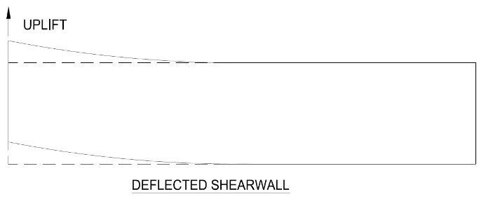
Method (1) really begins to break down when the shear wall panel is significantly longer then it is high. In this case, the wall is going to deflect under the uplift force and would therefore not be engaging its full dead load to resist.


Does anyone know of any testing or research done into how much of a wall dead load can realistically be expected to resist the uplift? I shudder to think of the strapping that will result from the use of method (2), but without some justification, do I have a choice?

Thanks for your help.
 
Replies continue below

Recommended for you

I talked to Ed Keith of the APA some years ago, and he told me it is perfectly fine to use all of the dead load which the wall supports to resist overturning (dead load times 0.6, of course).

Your method two seems to indicate a shear wall can "tear through" the diaphragm above--how could it if it is being held down by roof and/or floor framing?

DaveAtkins
 
I agree with Dave. I have used what amounts to your method 1 for years with no problems.

Mike McCann
MMC Engineering
 
The problem I see with method (1) is that when the shearwall panel is relatively long, the deflection in the wall will allow it to fail without utilizing all of the dead load it supports.

For example:

DEFLECTION.jpg


In this case only the dead load which is applied to the deflected section of the wall will be resisting the uplift. The remainder of the dead load on the wall does not seem to be helping.

Thoughts?
 
I would think that's correct since you're getting uplift at one end and compression at the other. The dead load will not help across the entire length of wall. That's my opinion. Maybe I'm not understanding your question.
 
I disagree. A wood shear wall is not one gigantic wall, but rather a series of 4' wide shear walls all trying to overturn. You can't develop a large uplift at the "back" end of the shear wall, because the dead load along the wall continuously holds down the 4' segments.

DaveAtkins
 
How do you justify using 4' shearwall segments for uplift?

I am assuming this is based on 4' wide sheathing panels.

I believe the point of all our calculations for nailing and blocking is to make the entire shearwall work as one unit.

In order to treat it as a series of 4' wide panels we would need to have hold downs every 4'. This is not a situation I have ever heard of as this would have a significant impact on the construction costs.
 
If your wall is is relatively long, your uplift force should be small. While they are not your main uplift anchorage, you will still have sill anchors helping.
 
Skazak,

You wouldn't need holddowns every 4' because the sum of the vertical forces in the stud you are holding is down is equal to 0. One 4' wall's tension chord is the adjacent 4' wall's compression chord.
 
Right, tngolfer. Each 4' wide segment, when it tries to overturn, is held down by the segment behind it.

DaveAtkins
 
I agree with using the entire wall, it works because the shear is transferred thru connections between adjacent panels. If you imagine one panel somewhere along the wall that is not attached to a stud along its vertical edge, then the idea breaks down. There is also compression force along the top of the wall and tension force along the bottom to represent the moment resistance along the length of the wall, but I have never seen this actually accounted for (anyone else ideas on this?). There are also chords at each END of the wall that are typically designed for.

Now if there was an uplift point load at the end of the wall coming from, I don't know an above story column or something external to the rest of the wall, I think you need to look a little more closely at the wall's behavior than what is normally done. The typical shear connections along the wall may not be enough to transfer the internal forces required to pick up the adjacent roof dead load along the entire wall's length (which would be required to resist the overturning induced from the external point load at one end).
 
What is the purpose of using holddowns but to prevent the "deflection" described above? - ie, prevent "rollover".

It is true that not all shear walls have holddowns, or need them, but they are usually pretty lightly loaded anyway with little uplift due to the long moment arm of the length, so the chance of that kind of deflection occurring in the real world is pretty minimal in my opinion.

I also concur with the 4' SW analogy presented above too.


Mike McCann
MMC Engineering
 
scratch that about moment along the length of the wall, don't know what the hell I was thinking there.
 
Status
Not open for further replies.

Part and Inventory Search

Sponsor

Back
Top