Eng-Tips is the largest engineering community on the Internet

Intelligent Work Forums for Engineering Professionals

Time History Analysis for Machine Foundation 1

Status
Not open for further replies.

LoneStarEngineer

Structural
May 4, 2016
37
0
0
US
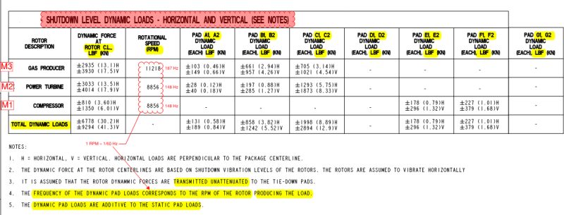
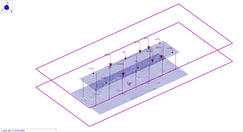
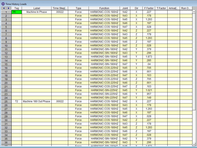
I have an elevated concrete platform modeled in RISA 3D and I am researching on performing a time history analysis for the structure. The equipment manufacturer has provided a set of dynamic loads at the rotor support points for both horizontal and vertical directions. I have assigned sine functions for vertical loads and cosine functions for horizontal loads. I have three machines, two running at the same frequency and the 3rd one running at a higher frequency. I also have cosine functions with 180 degree phase angle for a separate load case.

How does RISA handle load cases under a common time history tag? Should I define one time history tag with all the loads in X, Y and Z directions like below? I think keeping the load tags separate for each load direction would be more appropriate but wanted to get more opinions. Moreover, do I have to combine loads in horizontal and vertical directions within the same load tag?

Is there a good reference on which time history load directions need to be considered/combined together for a load case? Appreciate any inputs. Thanks.

Time_History_epri97.png
 
Replies continue below

Recommended for you

LoneStarEng said:
How does RISA handle load cases under a common time history tag? Should I define one time history tag with all the loads in X, Y and Z directions like below? I think keeping the load tags separate for each load direction would be more appropriate but wanted to get more opinions. Moreover, do I have to combine loads in horizontal and vertical directions within the same load tag?

If they're all assigned to the same tag, they're all applied together. It's like all the items in a moving load or in the same basic load case. Make sense?

Personally, I prefer to apply the load at the rotor locations and then use rigid links down to the anchor points so that I only have to apply the loads to one spot. The loads from each rotor. Though I'm not sure that will work for all situations.

Now, what you describe works fine either way. It's all about how best to organize it. If you think keeping all the Y direction forces together is easier to organize, then do it that way. If you think keeping all the anchor loads from a rotor together regardless of direction makes more sense, then feel free to do it that way.
 
Thanks Josh! In the case of "keeping all the anchor loads from a rotor together regardless of direction", wouldn't this effect the output to compare the maximum response amplitudes?
 
The way I look at it is the following:
1) The real load is from the rotor. It's a cyclic force whose DIRECTION varies with time. The magnitude may always be the same, but the direction varies with time. At some instance it is perfectly vertical and others, perfectly horizontal. But, most of the time, it is some component of the two.

2) Now, the rotor force make their way through the equipment to the anchor points. You want to make sure the anchor points are consistent with each other. Meaning they amplitude and direction correspond to what that original rotor force would impose on those support points for that particular point in time.

3) That's why I prefer to model the force at the CG of the rotor only. Because then I apply a sine load for Vertical and a Cosine load for horizontal, and I rely on my rigid links to determine whether the force at a support point is up, or down, right or left or some combination. It's just easier to keep straight in my mind.

4) If you model the loads at the anchor points, and you've properly modeled their magnitude, sign and phase, then your results would be the same as you'd get from item 3).

5) If you model the loads in different tags (say T1 for X and T2 for Y, T3 for Z), where you have all the horizontal X reactions in T1, Vertical Y reactions as T2, and horizontal Z reactions as T3, then that's fine. When you run an analysis you'd use a load combination that includes T1, T2, and T3 together. This would give you the same total results as 3) or 4).
 
Thanks for the detailed explanation Josh. The dynamic loads I received from the equipment manufacturer occur at the anchor locations (See below), which is the reason I want to model them there.

On point 4, you mention "sign" of the loads. Since I have the loads provided by the manufacturer at the anchor locations already, do I still have to worry about their sign? I agree modelling the loads at the rotor CG would take into account the couple at the anchor locations and their associated tension-compression signs.

Machine_Loads_i6h4rl.png
 
On similar lines, do you typically include a "Ramp Up" and "Coast Down" time within the harmonic load function? I have not yet seen this being applied in all the literature I've read on this topic.
 
"On point 4, you mention "sign" of the loads. Since I have the loads provided by the manufacturer at the anchor locations already, do I still have to worry about their sign? I agree modelling the loads at the rotor CG would take into account the couple at the anchor locations and their associated tension-compression signs."

Well, I would just want to make sure that the signs make sense. Like if the rotor force is going to cause an overturning moment, I want to make sure the vertical forces are equal and opposite (assuming symmetric anchorage points about CG) and that they correspond to a shear force in the direction of the horizontal reactions. Make sense? All I'm saying is "trust buy verify" that the loading you got from the manufacturer.
 
Regarding the Ramp Up and Coast Down aspects of a function like this:

Different companies do this different ways. The company I used to work for would identify any natural frequencies of the structure that the equipment would pass through before reaching it's operating frequency. Then, they would run an analysis of the equipment at THAT EXACT frequency and make sure the results wouldn't cause damage to the equipment or structure. This is basically saying, "The cost of the structure doesn't matter. Beef it up until it can take the dynamic forces."

I believe that was possible (usually) with these giant table top turbine generators. But, it may not work for all equipment. Certainly it's conservative, right?

The Ramp Up / Coast down is probably more applicable to more slender structures that wouldn't be able to withstand prolonged operation at the worst case loading. So, you try to determine how quickly / slowly the equipment will start up and then see what happens to the structure during that ramp up.

The challenge with a ramp up or coast down analysis (at least in a program like RISA) is that the time interval of integration is constant. If you're running it based on a single operating frequency, then you can set this to the most appropriate value. But, if the frequency of the input load is constantly changing, then the time step is not going to be what you want it to be a lot of the time. As a result, you can lose some accuracy in the Time History analysis..... Or, you end up setting the time step to something very low and your analysis takes forever. It's a tricky thing to balance. Whether it's worth doing kind of depends on how much extra information you get out of a Ramp up / run down and how important that information is to you.


Does this mean they were actually designing for resonance conditions for a certain time function even though this may happen for just a second of time? That would definitely be very conservative.

In my case, I have a table top but it is not very high (about 12' to top of slab) so it is not too slender.

My main concern with using a ramp up and coast down in my function is this: The load varies from 0 to X during the ramp up time with a constant frequency, this range of load magnitude less than X would not really result in peak response amplitudes. This goes similar for the Coast down analysis. So, I am trying to think of scenarios where this input would be useful? One scenario that comes to mind would be your earlier mention about designing at resonance conditions if this occurs during the ramp up/coast down, where one would check for appropriate loads occurring at that particular frequency in the function but this would require the frequency to vary or setting a really low time step as you suggested. My model takes 15 mins just to run one load case and I already have a total of 3 load cases bringing the total time to 45 mins.

The manufacturer in my case has not provided the start up and shut down time interval and has just provided the operating frequencies. I can ask for it but want to make sure I really need it.

 
LoneStarEng said:
Does this mean they were actually designing for resonance conditions for a certain time function even though this may happen for just a second of time? That would definitely be very conservative.

Yes, this is definitely conservative. Though they may have different "acceptance criteria" when they run it for frequencies that are not based on normal operation. There is a classic story that an engineer at that company told me once. I'll repeat it here:

The company performed the design of some equipment support (probably a table top foundation). They had a long, detailed "operation manual" that the mechanical engineers turned over to plant operations when the design was complete and the unit was set to begin operation. It this manual was a description about how they could expect some vibration / movement at a certain frequency, with instructions on how they should throttle through that frequency to avoid damaging the equipment or the structure.

Well, the operator never read the manual. And, when he noticed the movement / vibration, he got nervous. So, he left it there fearing it would get worse if he throttled up at all. But, he did complain to his supervisor who raised the issue with our company and our engineers. Obviously, our engineers pointed out their error and informed them to please read through the operations manual. But, that was only after the equipment had spent plenty of time running at the worst possible frequency!!​
 
Interesting as to how different people/companies interpret and incorporate "lessons learned" aspects from their previous projects.

Below is the model I have developed for my table top. The top slab is composed of 30" concrete plate elements, with 30" round columns and loads modeled at rotor anchor locations (I'll be doing another analysis where the loads are modeled at the rotor CG with rigid links). The platform is supported on a mat with piles. I've modeled the mat as 12" thick rigid plate elements and constrained the mat and elevated slab with rigid diaphragms. There is a spring boundary condition modeled at the CG of the pile group with the impedance values from DYNA 6.

Once the dynamic analysis is finalized, I will be switching the top slab with concrete beams to get the design reinforcement. I am thinking of detailing "beam type" reinforcement hidden within the 30" thick top slab.

Do you have any suggestions on this approach or would do anything different? Thanks for your insightful responses.

3D_TT_twayxn.png
 
"I've modeled the mat as 12" thick rigid plate elements and constrained the mat and elevated slab with rigid diaphragms. "

What do you mean by "rigid plate elements"? I'd use elements that represent the stiffness of the actual concrete. I don't generally like using "rigid link" type materials with plate elements. Just because the element formulation is a lot more sensitive for plates than for beams.

Also, the purpose of your diaphragms is what? I assume at the pile cap / foundation level, it's so that the slab is adequately connected to your dyna derived support springs. If so, that is probably okay.... provided that your elements aren't too rigid. Connecting multiple "rigid" elements (like diaphragms and rigid link elements) together can be problematic. The program is pretty good at identifying these problems when it does a static analysis. But, I'm not sure that it's as good about it for dynamic analysis. Therefore, you'd definitely want to run a static analysis using gravity forces just to check the model.

 
The elevated slab is modeled with concrete elements and foundation pile cap is composed of rigid plate elements (Plates with very high E value to increase stiffness). If I use concrete elements with their associated stiffness, I would get weird displacements throughout the slab since my boundary condition is just a single spring, with stiffness and damping values in all 6 DOF , at the CG of the piles. If I had modeled springs at each pile location then the concrete elements would have been sufficient. But then I am running multiple analyses by changing the spring constants for different frequencies so wanted to simplify the model there.

The purpose of the diaphragm at the foundation level is to constrain the nodes at the pile cap in the lateral directions and the flexibility of the rigid pile cap/foundation system is coming from the spring boundary condition. I think I modeled the rigid diaphragm at the top slab just cause its a regular shaped thick concrete slab but might just take it out.

I have already ran an equivalent static analysis with both gravity and static lateral loads to see how the model behaves and have not seen any issues.Thanks Josh!
 
Status
Not open for further replies.
Back
Top