Eng-Tips is the largest engineering community on the Internet

Intelligent Work Forums for Engineering Professionals

  • Congratulations waross on being selected by the Tek-Tips community for having the most helpful posts in the forums last week. Way to Go!

Tire Contact Area 3

Status
Not open for further replies.

Yochael1996

Civil/Environmental
Jul 21, 2020
21
0
0
US
Dear all,

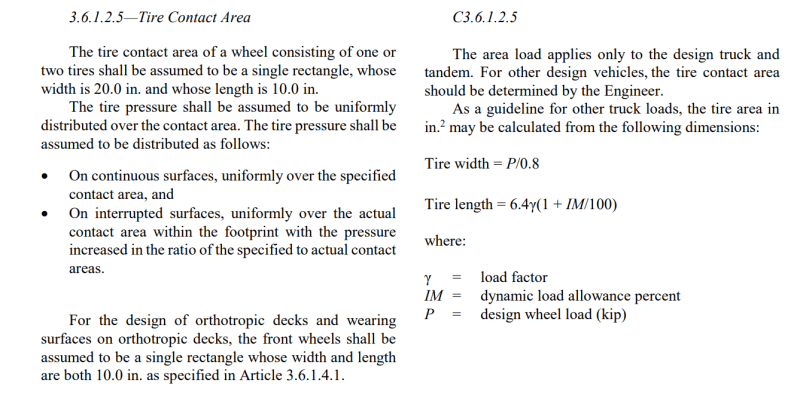
AASHTO LRFD for bridge design specifies the tire contact area for the design load as a 20in by 10in square. This dimension only applies to design load. I am wondering if there is a computation method to estimate the tire contact area for any random truck. I searched for some references and noticed that AASHTO LRFD 2nd Edition (1998) provides a set of equation:
Length=sqrt(0.004P), Width=sqrt(0.025P), where P is the load in pounds.
Are these equations still valid? Any references that can justify these equations or any new equations are appreciated!

Thank you in advance!
Best regards,
Yochael
 
Replies continue below

Recommended for you

Tire contact patch should be the tire load divided by the tire pressure. Apparently typical truck tires are roughly 100 psi on roughly maximum 4000 pounds of load, so 40 square inches.

sqrt(.004*4000 = 16) = 4
sqrt(.025*4000 = 100) = 10 and voila = 40 square inches.
 
Hi Dave,

Thank you for advising!
I am still a bit confused. Tire Contact Area = Load/Tire Presure (say 100psi), then how are these two equations (i.e., Length=sqrt(0.004P), Width=sqrt(0.025P))derived? I am asking because I am doing FEA for bridge decks and need to model the tire contact area, so the dimension is important.

Looking forward to your reply!
Thank you,
Yochael
 
In AASHTO LRFD Code 9th edition (2020):

Capture_nnjdll.png


These get a bit funky when you have smaller trucks - eg the H5 truck used in pedestrian bridges would theoretically have a 1.25" wide front wheel...
 
Not a clue. It's possible they went through the truck-tire catalog and found a best-fit equation. Only AASHTO can definitively answer the question.
 
Hi Gaston,

Thank you for replying!
I have reached out to the current AASHTO LRFD, but I am hesitant to apply this equation to a random truck because P, as denoted in the Commentary area, is the design wheel load. Do you know if we can use this equation for any routine commercial truck? Also, what are the suitable live load factor and IM for a non-design truck? It would be greatly appreciated if you can advise more!

Thank you,
Yochael
 
Yochael,

I agree. these generic equations should definitely be taken with a grain of salt. As I mentioned with a smaller truck they give you wheel widths that are better suited for a bike...

Would highly recommend going through Chapter 3 of the LRFD spec, you'll see the load factor varies based on your limit state (1.75 for Strength I, 1.35 for Strength II which is for special owner-specified truck) and is lower for other limit states. Similar with the dynamic allowance, it varies between 15% and 75% depending on what component and limit state you're looking at.

Is this for a fatigue analysis? Unless this is for a very detailed probabilistic model, I'd imagine you're probably better off using a conservative and simplifying assumption. Or maybe you can get away with a trip to your local truck stop, armed with a tape measure?
 
Hi Gaston,

It is not for fatigue analysis. I think of the same - using a simplified assumption. I try to justify the validity of the equations provided by AASHTO LRFD 2nd Edition (as described in the original thread). These equations are interpreted in terms of wheel load and is easy to be applied for any truck. The only issue is I am not sure if they are outdated... Do you have any clue on this? Thank you for the valuable recommendation!

Yochael
 
@Greg... specially with 'hard' wheels.

Rather than think climate change and the corona virus as science, think of it as the wrath of God. Feel any better?

-Dik
 
Status
Not open for further replies.
Back
Top