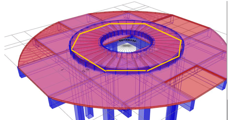
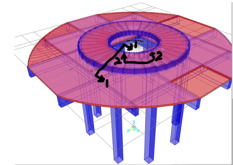
I want to add a circular beam and slab section on the top of the existing slab. But i am confused on how to create a connection between this two things. Should we assign constraints or is there some way to model it?
Navigation
Install the app
How to install the app on iOS
Follow along with the video below to see how to install our site as a web app on your home screen.
Note: This feature may not be available in some browsers.
More options
Style variation
-
Congratulations TugboatEng on being selected by the Eng-Tips community for having the most helpful posts in the forums last week. Way to Go!
You are using an out of date browser. It may not display this or other websites correctly.
You should upgrade or use an alternative browser.
You should upgrade or use an alternative browser.
To add a beam and slab section on the existing slab section 3
- Thread starter John188
- Start date
- Status
- Not open for further replies.
- Thread starter
- #2
I want to add a circular beam and slab section on the top of the existing slab. But i am confused on how to create a connection between this two things. Should we assign constraints or is there some way to model it? said:The beam and slab section would seem like this
-
1
- #3
- Thread starter
- #4
Physically you shall provide shear connectors between the ring beams and the slab to make it a composite structure. On computer modeling said:Thanks for your reply. Are you talking about the constraint? As the new beam slab element is supported on the slab i am not sure on how to assign constraint in such scenario.
-
1
- #5
MegaStructures
Structural
Pretty interesting structure you got here. What’s the point of adding the slab/beam? Does the existing slab not have sufficient strength, or is it some sort of architectural feature?
My attempt below:
Modeling offset shell elements with rigid links would be quite difficult (impossible?)if that’s how you are modeling your slabs. You could either model the slabs as one layer of shell elements with thickness properties equal to both, or if your program allows you can “glue” or “weld” the faces of the shells together, offset beams could be connected together with rigid links.
The major assumption you would making here is that there is sufficient mechanical anchorage to allow the slabs to work as one composite. That would need to be checked by hand.
“Any idiot can build a bridge that stands, but it takes an engineer to build a bridge that barely stands.”
- Thread starter
- #6
Thanks for your suggestion. As a new liner is being placed over the slab the existing slab is not able to bear the load so extra thickness is provided at that circumference which will help distribute the load and prevent punching. Actually the new liner load is a circumferential load and i distribute it to a new slab.[/quote]
- Thread starter
- #7
The major assumption you would making here is that there is sufficient mechanical anchorage to allow the slabs to work as one composite. That would need to be checked by hand. said:Physically you shall provide shear connectors between the ring beams and the slab to make it a composite structure. On computer modeling said:I provide the constraint at the lower beam and the new beam and slab. however, the two slabs are deforming in different method on analysis. Is there any way to connect two slabs together?
MegaStructures
Structural
John said:the existing slab is not able to bear the load so extra thickness is provided at that circumference which will help distribute the load and prevent punching. Actually the new liner load is a circumferential load and i distribute it to a new slab
I'm sorry this doesn't make sense to me. How is the load of concern applied? It's a circumferential load? Some sort of fluid pressure? Explain how load is transferred into the slab.
“Any idiot can build a bridge that stands, but it takes an engineer to build a bridge that barely stands.”
- Thread starter
- #10
Can you provide cross sections with note on member material and size? said:I'm sorry this doesn't make sense to me. How is the load of concern applied? It's a circumferential load? Some sort of fluid pressure? Explain how load is transferred into the slab. said:i have attached the cross section of the structure. Actually, the liner is supported on the centre beam which trasfers load to the slab and the lower beam and column
Allow me to ask few more questions.
1. Is the addition a concrete circular slab, or concrete ring beam?
2. Do you need to make the new and old structures fully composite, or just a simple connection?
3. How thick is the existing concrete?
1. Is the addition a concrete circular slab, or concrete ring beam?
2. Do you need to make the new and old structures fully composite, or just a simple connection?
3. How thick is the existing concrete?
- Thread starter
- #12
1.The circular slab and beam both are added on the existing slab.
2. I prefer the new and old structure fully composite. The structure must be fully composite, isn't it? Recently, while modelling i apply constraint of new slab with the beam and not the slab. This is reason why two slab are moving indepedently and not as a single structure. I am not able to constraint two slab.
3. The thickness of existing slab is 150mm supported on beam section as shown in figure
-
1
- #13
Presumably if the existing beams can take the vertical load in that arrangement, then do you need to connect it with anything but some nominal drilled in bars. Or do you need it to be composite to take the applied new loads and that the question over how to connect to act compositely? Any uplift from the tank or whatever it is might change this, but need more explanation around the arrangement to know this.
I can't help but think it would be a whole lot easier to have a series of straight beams/cages supported from the existing beams as shown below (and similar to the internal hole (not shown on sketch))? Slab just spans between these new beams or cantilevers past slightly?
Then just model the applied loads on the existing structure. Design new slab for applied loads, existing for applied reactions. Keep it simple, any composite action you get is a bonus.

Actually looking at the plan you just attached while I was writing last reply, if you were to go with my suggestion, all the new beams can be directly over the columns. This seems far simpler than the curved cages you are implying will be used via what has been modelled?
- Status
- Not open for further replies.
Similar threads
- Replies
- 11
- Views
- 10K
- Replies
- 3
- Views
- 7K
- Question
- Replies
- 7
- Views
- 1K
- Replies
- 6
- Views
- 4K

