Luis Ernesto Quiroz
Automotive
Hello,
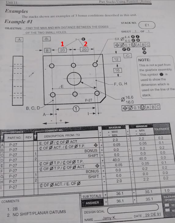
In Alex Krulikowski Workbook Unit 11 Example #1 basic dimensions 20 (1) and 20 (2) are add up and considered as 40 basic ignoring the position and bonus of the central hole and only considering the position and bonus of the initial and final holes (condition 1B):

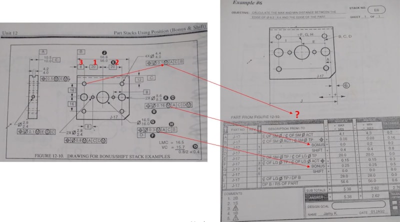
However, in Unit 12 Example #6 dimension 20 (2) does considers the position and bonus (condition 1B) and again neither basic dimensions 20 (1) nor basic dimension 8 (3) considers the position and bonus of the hole between 8 and 20 (condition 1B).

My questions are:
1. considering note #5 in Bonus/Shift Chart "Stacks using chained position callouts must include a location tolerance for each callout" does an additional feature control frame for the hole between basic dimension 20 and basic dimension 8 need to be add to consider its position tolerance and bonus on the tolerance stack up?
2. Would everybody agree that this drawings are only for academic purposes and real drawings should show basic dimensions for each hole against datums B and C and not between features?
Thanks a lot for your comments on this post!!!
Luis Ernesto Quiroz
Mechanical Designer.
In Alex Krulikowski Workbook Unit 11 Example #1 basic dimensions 20 (1) and 20 (2) are add up and considered as 40 basic ignoring the position and bonus of the central hole and only considering the position and bonus of the initial and final holes (condition 1B):

However, in Unit 12 Example #6 dimension 20 (2) does considers the position and bonus (condition 1B) and again neither basic dimensions 20 (1) nor basic dimension 8 (3) considers the position and bonus of the hole between 8 and 20 (condition 1B).

My questions are:
1. considering note #5 in Bonus/Shift Chart "Stacks using chained position callouts must include a location tolerance for each callout" does an additional feature control frame for the hole between basic dimension 20 and basic dimension 8 need to be add to consider its position tolerance and bonus on the tolerance stack up?
2. Would everybody agree that this drawings are only for academic purposes and real drawings should show basic dimensions for each hole against datums B and C and not between features?
Thanks a lot for your comments on this post!!!
Luis Ernesto Quiroz
Mechanical Designer.
