Continue to Site

Eng-Tips is the largest engineering community on the Internet

Intelligent Work Forums for Engineering Professionals

  • Congratulations pierreick on being selected by the Eng-Tips community for having the most helpful posts in the forums last week. Way to Go!

Tolerance feature interpretation? [updated, question added] 2

Status
Not open for further replies.

jmdlok

Electrical
Nov 21, 2017
10
Hi there,

Can somebody please take the time to explain the relevance/correct interpretation of this tolerance feature? I'm not a mechanical engineer by training (electronic), so this is all a little new to me.

Sample_Engineering_Drawing_qzbjuo.png


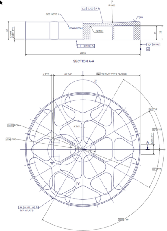
The drawing declares general tolerance to ISO 2768-M. I'm specifically referring to the tolerance feature for the three flat zones (bottom left)

My interpretation is that the flat has a zone of tolerance associated with it of +-0.1 units, in terms of its width with reference to its midpoint.

Any help is appreciated.
 
Replies continue below

Recommended for you

Your drawing is made in accordance to ISO set of standards.
Unlike American (ASME) system, ISO allows use of "Position" control with nominally flat surface.
The meaning should be explained on the enclosed picture.

The surface should be within tolerance zone 0.100 wide.


"For every expert there is an equal and opposite expert"
Arthur C. Clarke Profiles of the future

 
 http://files.engineering.com/getfile.aspx?folder=b58256d1-1d34-4dd1-9f72-65c52b6a9f54&file=Capture.JPG
CheckerHater said:
The surface should be within tolerance zone 0.100 wide.

Great! I suspected this was the case, thank you for linking the relevant ISO standard.

There are some other foreign parts of this drawing to me. Is it OK to ask them in replies to this post or is it a forum rule to ask them in separate posts?
 
Imsavk:

I am more familiar with ASME Y14.5 (USA) than ISO (European) standards, but I am pretty sure you can apply position to flat surfaces within ISO conventions - which you cannot do within Y14.5 - where position can only be applied to features of size (cylinders, spheres, and sets of parallel planes). So I will ignore this issue and accept the ISO interpretation.

Also, Datum B is not identified. So the relationship between it and the three flats cannot be evaluated.

My interpretation: the design requires three flat surfaces on the OD, at 127 (linear) from the center of datum feature A (resulting in the 22.6 wide calculated reference dim) and with some other (undefined) relationship to Datum B. The .100 wide tolerance zone is "centered" on the 127 BASIC dimension and is a total zone - .05 less than 127 and .05 more than 127 and not +/- .1 as you stated.


Certified Sr. GD&T Professional
 
Glad to be of any help.

About your question - I guess it's totally up to you.

If you think two questions are related, you could ask them within the same thread; if you are afraid it could be confusing - start another one.

It's quite often threads are drifting away, getting hijacked (sometimes unintentionally) or split in two.

As long as you mean well you are welcome.

"For every expert there is an equal and opposite expert"
Arthur C. Clarke Profiles of the future

 
Status
Not open for further replies.

Part and Inventory Search

Sponsor