Continue to Site

Eng-Tips is the largest engineering community on the Internet

Intelligent Work Forums for Engineering Professionals

  • Congratulations IDS on being selected by the Eng-Tips community for having the most helpful posts in the forums last week. Way to Go!

Tolerance of + and - versus ± 1

Status
Not open for further replies.

Chapin Paullin

Automotive
Feb 23, 2017
2
Engineers,

I have a question regarding tolerancing that I see all the time. On prints I will often see dimensions toleranced unevenly. Why do some engineers give a base line dimension, let’s say 14.125 Inner Diameter of a print. The tolerance will read + 0.025 and – 0.005 (total of .030 tolerance or ± .015). This would mean the Max dimension is 14.15 and the Min is 14.12.

Therefore, would it not make sense to address the dimension as 14.135 ± 0.015? Why would an engineer choose 14.125 + 0.025 – 0.005 over the cleaner 14.135 ± 0.015?

Any insight would be helpful.

Chip
 
Replies continue below

Recommended for you

If the product performance degrades more in one direction versus the other or you care more about one limit versus the other (from the nominal baseline) then, probably, (I say only probably), it is a good practice.
You want to give manufacturing as much tolerance as functional possible so “the other side” (the side you care less) should be more “relaxed”- from the ideal/perfect part--, but certainly not beyond of the point of diminishing returns.
 
They do it because they can. And not always the best way.

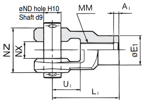
Let say you have a knuckle joint:

Capture_u4ia31.png


Both clevis and pin have nominal diameter 25 mm, but in order to function properly, pin has to be made to d9 and clevis has to be bored to H10.

So the pin is now 25 -0.065/-0.117, and clevis 25 +0.084/-0. This maintains the fact that both parts are nominal 25, but creates confusion to some people.

The other (and best in my opinion) way is to use limit tolerances combined with ISO symbols: Pin 24.935/24.883(25d9), clevis 25.084/25.000(25H10). This combines best of both worlds - limits for manufacturer, design intent for engineer.

And (again - in my opinion) the most confusing way would be convert the limits into "plus and minus" way: Pin 24.909 +/-0.026, clevis 25.042 +/-0.042. Meaningless bastard numbers.

"For every expert there is an equal and opposite expert"
Arthur C. Clarke Profiles of the future
 
CheckerHater may think clevis 25.042 +/-0.042 is a meaningless bastard number but I guarantee you that is what any process engineer worth his standard deviation is going to use. For most processes with a statistically normal distribution, they are going to want the average right in the middle of the tolerance for the best possible process capability. You can dimension it anyway you like but they are going to aim for the middle.

----------------------------------------

The Help for this program was created in Windows Help format, which depends on a feature that isn't included in this version of Windows.
 
I believe that the use of nominal with bilateral equal/unequal or limit dimensioning should be utilized in whatever capacity the designer feels best communicates functional intent. As CH pointed out a common application of this is with standardized fits, as the tolerance values are often unequally disposed about the nominal. These could be changed to equally disposed bilateral tolerances, but would I think would have to forego the standardized nomenclature to prevent confusion.

Regardless, to add to what dgallup said - the stated nominal unless noted is not a manufacturing target. The production floor will target whatever nominal value allows them to most easily produce in-spec parts, typically right in the middle of the tolerance zone.

If you follow ASME rules in Y14.5-2018 section 4.1 this is stated as the following:

"(q) UOS by a drawing/model note or reference to a
separate document, the as-designed dimension value
does not establish a functional or manufacturing target."
 
I would aim for middle of the tolerance zone when programming CNC (and I did), but I would never put it on the drawing (and I didn't).
Just my ¢2

"For every expert there is an equal and opposite expert"
Arthur C. Clarke Profiles of the future

 
dgallup said:
For most processes with a statistically normal distribution

I would argue that any process engineer worth his standard deviation will know, either from direct statistical confirmation or through a well-honed understanding of the processes for which he or she is responsible, what type of distribution they should expect. There are a LOT of common processes that can very easily be tuned to produce non-normal distribution of results, which in many circumstances is desirable.
 
Chapin Paullin,

In CAD, I prefer to model things at nominal dimension, and apply tolerances. This can result in the sort of tolerances you are describing. This can happen when you specify the ANSI fits from the Machinery's Handbook. I like to call up the +[ ]and -[ ]tolerances on my drawings so that the nominal as-modeled dimension is shown explicitly.

This all works fine if your fabricator works from the drawings. If there is any possibility of fabrication straight from the model, you must model at median profile, and specify [±][ ]tolerances. Obviously, rapid prototyping works this way. I work with a boss who likes to send DXF files out for waterjet cutting. I am also seeing solid models sent out the Xometry and Protolabs.

--
JHG
 
If you cant handle addition and subtraction, there are other jobs to be had. Go be a lawyer or journalist.
 
Some purchased "precision" products are manufactured to a nominal + something - nothing.

The tooling that might be used to machine the mating part (at least in olden days ) is made accordingly.
Note reamers are available in small increments either side of the nominal, to easily create a hole with the intended fit.

It makes designing and manufacturing the mating part much easier.

Even in these CNC days changing tools is expected.
Up to 40 tools, which might include reamers, taps, etc, I'm guessing.
 
Why give a nominal value that is not in the middle? Because a very old piece of paper (eng standard) says so. Also, because the shop likes it that way.

Machinists do like to know what the actual target value is. If you give a target with a wide tolerance (symmetric or asymmetric) and the machinist can easily get close to the target, they will. If you give them limits of size with no target, the machinist will shoot for the middle.

If you've re-translated an assymetric tolerance to be symmetric, then you are going to get a different distribution of sizes after 1,000 parts have been made. This might be bad. If you are making only one part, it probably doesn
t matter.

Shaft and pin fits will even require tolerances of nominal minus some and minus a little more. E.g. 1.0000 -.0001 -.0002 per the spec. I personally would detail dimensions like these as limits of size, .9998-.9999. I'm with CheckerHater on this. If your specific application has a specific standard, stick to the standard. Don't translate tolerance bands into symmetric bilateral tolerances just for the sake of being able to use the +- symbol.

Nominal and bilateral, limits, nominal and asymmetric tolerance is topic that never ends. Fab and engineering are never going to agree. Guaranteed you are going to argue about this for the rest of your life. (Unless your outfit just writes down what is expected in a drafting manual.)
 
Status
Not open for further replies.

Part and Inventory Search

Sponsor