Continue to Site

Eng-Tips is the largest engineering community on the Internet

Intelligent Work Forums for Engineering Professionals

  • Congratulations waross on being selected by the Eng-Tips community for having the most helpful posts in the forums last week. Way to Go!

Tolerance problem when trimming an Extruded Solid

Status
Not open for further replies.

phaifleigh

Automotive
Sep 30, 2014
11
Hi, I am newer to NX first off. I am having a problem that I would so appreciate some help with. I am trying to take a Class A side Styling surface(Automotive Trim Parts),Sew them together, everything good so far. Then take the trim lines(boundry curves ot surface, parting lines} of that surface and project them onto a plane, normal to my Die Direction. Then Extrude those trim lines back through the actual trim lines(along the die line), so I can then trim the Extrude with my Sewn Surface and Shell in my part thickness. The problem I am having is NX won't Trim the Extruded Solid with the Sew Surface, says the two do not intersect at the trim lines and the edge of the extrude. Of course they do though. Even if I loosen the tolerance value in trim body forever, it will not trim it. Are there some Tolerance issues I need to know about or what? I really want this to work. help please!
 
Replies continue below

Recommended for you

In NX You can extrude the curves without making them planar.
try extrude what you have without the "project to plane" step. - adding this project step will only add to the total deviation.

Make sure that the trimming surfaces oversize. Then trim.

Regards,
Tomas
 
Thanks for answering Tomas. When I extrude curves not on a plane, I don't get a Solid and I do have the Body Type set to Solid. Is there something I'm missing. Also, the reason I was trying to do it this way was to avoid extending surfaces, that wont stay connected. I just can't believe this system can't do this. Any other suggestions are appreciated.
 
The way you described seems to be too complicated.
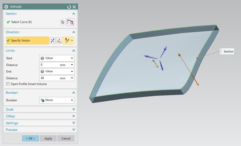
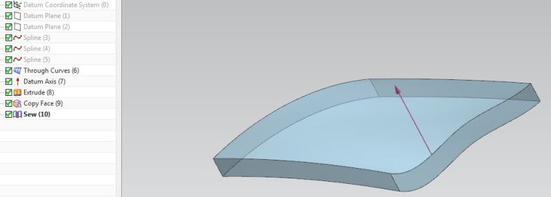
You're able to thick a surface via Extrude it boundary curves along any vector. Is the picture shows what you need?

1_yunzvh.jpg

2_fbzhqa.jpg


1. The Datum Axis defines a Die Vector
2. Make an Extrude with outermost boundaries along the vector. The result would be a Sheet Body
3. Then copy top face along the Die Vector in order to "cover" the Sheet Body from the bottom
4. Sew both Copied Face and Sheet Body
5. The result should be a Solid
 
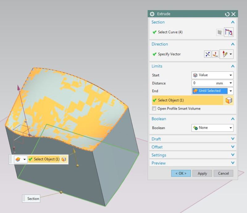
The other way is to use an Extrude limits instead of Trim body:
After you made a boundary projection onto a plane along a die vector - extrude it with end limit set to Until selected:

1_pzyv3l.jpg


Also try to use the Emboss Body feature, it would also helps.
 
NX can probably do it, you're more than likely not doing it correctly - no offense intended - you did admit you're new to NX.

Not extending the surfaces beyond what's necessary could be the issue. It's typical best practice to over extend surfaces or bodies the majority of the time, regardless of the software being used. It makes it easier for the system to approximate edges when you go beyond the intended boundary. If you try to fight it, you're going to spend way more time attempting to force it to work than what it's worth.

You can take the existing surfaces, Extract an associative copy of all of them and then extend all the outer edges beyond what's necessary (outside of your Extrude) then Sew the extended surfaces together and Extrude up to the extended sewn surface like Lockdain has shown but if you have more than 1 surface, it won't work - you'll have to Extrude beyond the sewn surfaces and then use Trim Body.

Without seeing the part and what all you're trying to do or a similar part, our responses are going to only be best guesses.

Tim Flater
NX Designer
NX 9.0.3.4 Win7 Enterprise x64 SP1
Intel Core i7 2.5GHz 16GB RAM
4GB NVIDIA Quadro K3100M
 
Thanks for the suggestions Gentleman. Very much appreciated. To Xwheelguy, I tried to Extrude up to the Sewn Surface, and as you suggested, it needs to be one surface. This seems to be the problem, the Sew surface of multiple compound surfaces. There seems to be a tolerance issue with the Sew surface, where as I cannot Trim the Extrude with it or Extrude up to it either. I really don't want to get into extending surfaces. It has other problems built into it. I have found that if I recreate the Sew surface with Through Curve Mesh (and then do a Refit Face to resmooth the surface)I can Trim the Extrude(created with the surface trim lines)with the Surface. So my question is: Is there a NX function which will "Convert" the Sew surface to a single surface entity (with point clounds or something). I ask because not all surfaces I work with are curvature basically running in one direction but surface's with curvature running in multiple directions, for example, a shape like the letter (T). Know what I mean? Plus, the Refit Face does a pretty nice job but did pull away from my original surface by 1.3mm in areas. Again, I'm not looking to recreate the Sew surface, but to Convert it if possible. May not be. I spoke to a Siemens Rep, and was no help at all. Thanks for the interest. Patrick.
 
I'm not sure about the 'extrude to' option, but you should definitely be able to use sewn sheets in a trim body operation (assuming the sewn sheets extend beyond the solid body). If the trim body operation gives an error when attempting to trim a solid body, I'd suggest running the 'examine geometry' command on the sheets to make sure there are no geometry errors in the sheets/solid.

www.nxjournaling.com
 
Instead of “Until Selected”, if you use “Until Extended” option, the trimming face (a single face = plane) could be anywhere and smaller than the extruding boundary.

In an assembly environment, you could use Until Selected/Extended to an external object’s Plane/face/surface with the option of automatically creating Interpart Link (Associative/non- associative).

Optionally to trim face and also when the surface (larger than the extrusion) isn’t intersecting the extrusion, you could use Sync Modelling's Replace Face.


Michael Fernando (CSWE)
Tool and Die Designer
Siemens NX V10.0 + PDW
SWX 2013 SP3.0 X64
PDMWorks 2013
Logopress3
FastForm Advance
FormatWorks
 
I don't quite understand what you're trying to do, but if you're trying to take a contoured surface and extrude down to a planar base (to make a die section) then I would extrude the outside edges in the direction you want to go far enough so that the longest part goes beyond where you want to be (this will be a sheet body), then "Trim Body" to the plane you want, and then add a "Bounded Plane" to the open end, and then "Sew" it all together.
 
You may be right Cowski, it may be the data is not clean enough. I'm getting the data from another source and possibly another cad system. I created some clean surfs and sewed together and was able to trim Extrude with sewn surface. Also, did not have to extend the surfs, which is what I'm trying to not have to do. See, I'm using the trim lines of my surface, projecting onto plane and extruding back thru trim lines. Then trimming extrude with Sew surface. Thanks for your interest. going to have to get into matching edges and tangentcies.
 
When you import geometry from another source, I recommend running the synchronous command "optimize face" and/or the "heal geometry" command (file -> export -> heal geometry) before attempting to work with it. These commands can help clean up some minor imperfections with the imported geometry.

www.nxjournaling.com
 
Wow, Awesome info, thanks. I will give that a try!
 
Nope, didn't work optimizing and healing data. Even extended surfs. Would trim with the sew. I can create my own clean surfs and sew and it does work. Too bad I can't convert a sew surf to a single entity surf.
 
Then you have surfaces with gaps that exceed your modeling tolerance. Examine geometry will give you the feedback as to where and what issues are present. Either those issues need to be addressed or you're modeling at too tight of a tolerance - modeling tolerance is objective, but I don't like going over 0.025mm with 0.01mm being the max I prefer. Some of that will depend upon the type of industry for which you're working. A long-time former Siemens employee once recommended using a modeling tolerance which was 10% of the tightest (smallest) manufacturing tolerance. Now that we're getting into the tolerance discussion, don't take that as "Oh, I can change this tolerance for this feature and now it all works". That's not recommended - pick a tolerance, set NX to use that tolerance and try not to change it if at all possible. Don't get into the habit of changing the tolerance feature by feature - that's a bad habit.

You can't convert sewn surfaces into a single surface? Sure you can - look at Quilt. Keep in mind, Quilt may not be a 100% 1:1 "conversion" - there might be some tolerancing used to create the resulting single-faced surface. Quilt can be a bit touchy, depending upon the complexity of the starting sewn surfaces. What I usually do is once I get a Quilt to work, extract the isoparametric UV curves of the Quilt surface to create a curve mesh (the UV curves do NOT need to be associative) then create either a Through Curve Mesh surface or Studio Surface using the extracted UV curves. I don't feel it's necessary to keep the "old stuff" around if it's not going to be used.

Don't take offense, but it sounds like you might benefit from some training to get familiar with what NX commands will fit your modeling workflow(s).

Tim Flater
NX Designer
NX 9.0.3.4 Win7 Enterprise x64 SP1
Intel Core i7 2.5GHz 16GB RAM
4GB NVIDIA Quadro K3100M
 
In case some are wondering why I'm trying to do this: I have B-side features on these parts; ribs, doghouses, etc. and my A-side surface changes all the time, so I want to be able to switch out my A-Side surface and have my B-Side features automatically update to the new resulting B-Side surface(because the extrude is Shelled).

To Lockdain: I may have to try what you're saying. I guess when I get a new A-Side Surface, I could Edit with Rollback on the Sew, and deselect all the Sheets and select all the new Sheets. I'll have to try it.

To MFDO: I'll have to look into what you are saying, but when you say Single Face = plane, are you understanding that I son't have a single face or a plane? I have multiple curved surface Sewn together.

To XWheelguy: I will try the Quilt today, extract the UV parameters and rebuild the surface and see how much it deviates from original surface.

Thanks all very much for suggestions!
 
If the Quilt works, then you might revisit the Extrude with End Limit set to Until Next or Until Extended.

Tim Flater
NX Designer
NX 9.0.3.4 Win7 Enterprise x64 SP1
Intel Core i7 2.5GHz 16GB RAM
4GB NVIDIA Quadro K3100M
 
One trick that I hate to use, but occasionally comes in handy as a quick fix in these situations, is to extrude the shape up through the sheet, offset the perimeter faces in a small amount, trim the extrusion to the sewn sheets, and offset the perimeter faces back out by the same amount. This trick should work if the error you are seeing is due to the sheets being the same size (or slightly smaller) than the extrude (due to tolerant edges or other approximations).

www.nxjournaling.com
 
phaifleigh, maybe you're able to provide us with some examples that illustrates your issue? I think now i understood your problem, but i'm not sure.

 
Status
Not open for further replies.

Part and Inventory Search

Sponsor