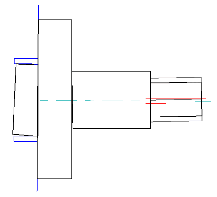
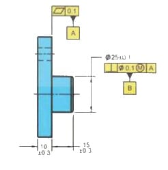
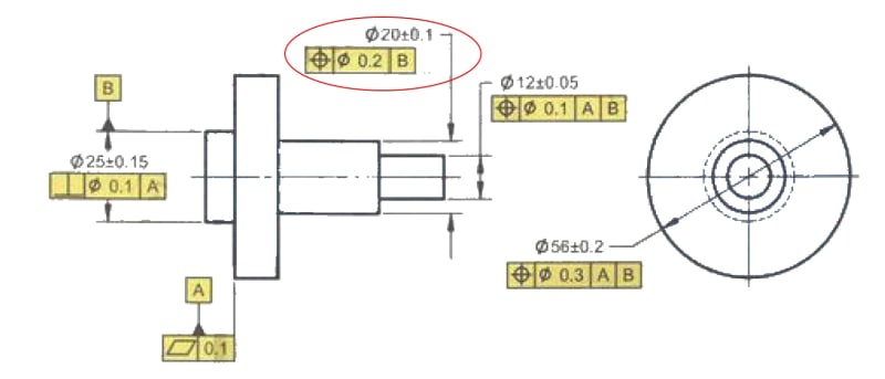
This came up on one of the drawings recently but I see it all the time, even in the textbooks. Say you have one circular feature with a perpendicularity constraint to a datum defined by a flat face and then you have another circular feature coaxial with the first one and having true position defined for it. For example Ø20 below
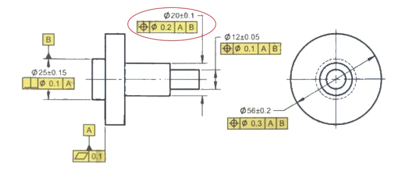
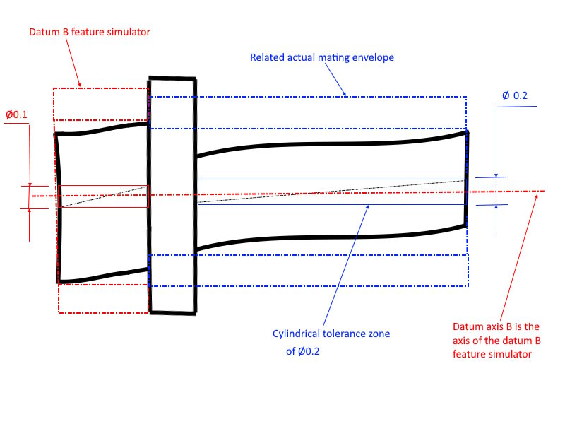
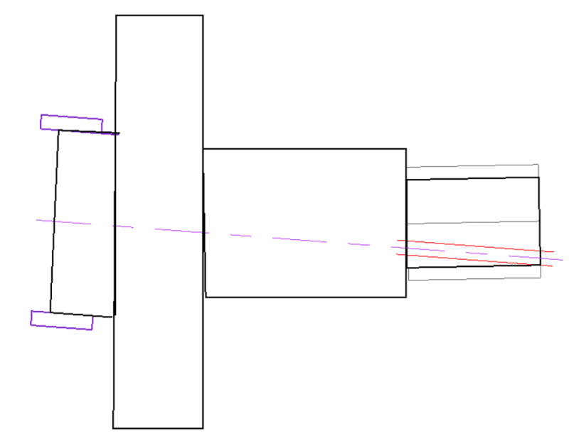
It is using two datums and establishes coaxiality to datum B and perpendicularity to datum A. My issue with that is that, the way I see it, using datum A doesn't add any additional constrain to the drawing. It defines exactly the same cylindrical tolerance zone around datum B axis, which is already perpendicular to the datum A. In other words, removing datum A from the feature control frame for that dimension will not affect the feature's tolerance zone at all... or am I missing something?
It is using two datums and establishes coaxiality to datum B and perpendicularity to datum A. My issue with that is that, the way I see it, using datum A doesn't add any additional constrain to the drawing. It defines exactly the same cylindrical tolerance zone around datum B axis, which is already perpendicular to the datum A. In other words, removing datum A from the feature control frame for that dimension will not affect the feature's tolerance zone at all... or am I missing something?


![[smile]](/data/assets/smilies/smile.gif "[smile] [smile]")