Continue to Site

Eng-Tips is the largest engineering community on the Internet

Intelligent Work Forums for Engineering Professionals

  • Congratulations waross on being selected by the Eng-Tips community for having the most helpful posts in the forums last week. Way to Go!

Tolerance zone for true position of coaxial features 1

Status
Not open for further replies.

Diametrix

Aerospace
Jan 31, 2023
50
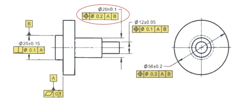
This came up on one of the drawings recently but I see it all the time, even in the textbooks. Say you have one circular feature with a perpendicularity constraint to a datum defined by a flat face and then you have another circular feature coaxial with the first one and having true position defined for it. For example Ø20 below
Example_1_obeal8.jpg


It is using two datums and establishes coaxiality to datum B and perpendicularity to datum A. My issue with that is that, the way I see it, using datum A doesn't add any additional constrain to the drawing. It defines exactly the same cylindrical tolerance zone around datum B axis, which is already perpendicular to the datum A. In other words, removing datum A from the feature control frame for that dimension will not affect the feature's tolerance zone at all... or am I missing something?
 
Replies continue below

Recommended for you

OP said:
....What if the datum B is a secondary datum in the FCF, but primary is some other cylindrical datum, let's say C. ....

You have to ask yourself: what would be the physical realities of the assembly that will determine/force that B will act as primary in one case, but B will act as secondary in the other case?

 
Diametrix said:
Are you saying that datum axis B changes depending on the fact that some other feature references datum B or not?

Of course not. It's not about what the control for some other feature references. It's about what the control for the feature in question references.
Perhaps I didn't express it clearly enough.
"Datum axis B is the axis of the unrelated AME if only datum feature B is referenced" means: If the feature control frame for the considered feature references only datum feature B, datum feature B acts as the primary (and only) datum feature for that control. Therefore, the "unrelated AME" is used as the datum feature simulator. If datum feature B is not the primary datum feature but referenced secondary or tertiary, then as I explained and Evan explicitly named it - the "related AME" (an envelope constrained in orientation and possibly location to preceding datums) is used as the datum feature simulator. Different datum feature simulation means different fixturing for inspection and different results of measurements.
 
Diametrix,

If I understand your question correctly, the answer is yes. The simulator for datum feature C would be its unrelated AME (because C was referenced as primary in this FCF), and the simulator for datum feature B would be its related AME (because B was referenced as secondary in this FCF).

The logic behind this arrangement is that the sequence that the datum features are referenced in is supposed to mimic the sequence that the part features are contacted in during assembly.

Evan Janeshewski

Axymetrix Quality Engineering Inc.
 
Diametrix,
I agree with Evan's explanation above, but in the context of the part in your example, note that using two cylindrical features as primary and secondary datum features in the same feature control frame only makes sense if they are NOT nominally coaxial. So that is not a suitable scheme for your example. If they are coaxial - the secondary datum feature and simulator would not be able to impose any constraints of degrees of freedom that remain unconstrained after the primary datum is simulated.

Another thing is, that I want to clarify and expand my latest explanation to you about the datum feature simulator constraints (which is, as you were told, what sets the orientation and possibly location of the entire part relative to the datums and tolerance zones). As Evan indicated too, the constraints that act or do not act on the datum feature simulator are unique not even per feature, but per feature control frame. For example, you can control the same feature by two single segments tolerance of position, which is essentially two separate feature control frames, in which the upper one could reference A, B with a larger tolerance value and the lower one could reference B only with a lower tolerance value. For the tolerance conformance evaluation of each feature control frame, the relationship between datum feature B (and the entire part) and datum feature simulator B plus the axis derived from it would be different, and the measured value for each requirement will be different too.
 
This makes sense to me finally. Sorry it took so long. Thanks guys for all your explanations!
 
The way this is expressed is as [B-C], to use the combination of the two, and it creates a single axis for two nominally coaxial diameters.

In 2009 I don't recall a special term for it the combination, just "multiple". In 2018 they call it a "common" datum feature. Unfortunately that term is also applied to other conditions in 2018.

I'd have called it a compound datum feature reference.
 
Diametrix,

I'm glad that it makes sense now.

3DDave,

I'd have called it a composite datum feature reference ;^).

Evan Janeshewski

Axymetrix Quality Engineering Inc.
 
Sure, but composite is used liberally already. Compounds are already known to be a mix of two or more things.
 
3DDave,

The winking emoticon was supposed to signify a non-serious response. I realize that "composite" is already used in a completely different context in Y14.5 and so using it would make things more confusing. How about "group datum feature" ? ;^)

I was actually fine with "multiple datum feature" from '94 and '09, and I'm not sure why they changed it. I would agree that "compound datum feature" would have been a better term than "common datum feature".

Evan Janeshewski

Axymetrix Quality Engineering Inc.
 
The weird thing is "multiple datum" really didn't get used in context; where it was used didn't refer to the use of two differently identified features, but to elements of a pattern used as a single feature. It could have been "multi-datum datum features" which is a mouthful.

"common datum" is used in multiple contexts and not restricted to using separately identified features as a single one.
 
It's already been many different thing except "composite":

1982
Compound Datum Features. (Para. 4.4.5)
Where more than one datum feature is used to establish a single datum, the appropriate datum reference letters, separated by a dash, are entered in one compartment of the feature control frame.
Pattern of Features. (Para. 4.4.6)
Multiple features of size, such as a circular pattern of holes at MMC, may be used as a group to establish a datum when part function dictates… When the part is mounted on the primary datum surface and rotated about the centroid of the secondary pattern of holes, a central datum axis (axis of rotation) is generated for establishing the datum reference frame.
1994:
Multiple Datum Features. (Para. 4.5.7)
Where more than one datum feature is used to establish a single datum, the appropriate datum reference letters and associated modifiers, separated by a dash, are entered in one compartment of the feature control frame.
(further explained in the: 4.5.7.1 Simulation of a Single Datum Plane; 4.5.7.2 Single axis of Two Coaxial Features.)
Pattern of Features. (Para. 4.5.8)
Multiple features of size, such as a pattern of holes at MMC, may be used as a group to establish a datum when part function dictates… When the part is mounted on the primary datum surface, the pattern of holes establishes the second and third datum planes of the datum reference frame.
2009:
Multiple Datum Features. (Para. 4.12)
Where more than one datum feature is used to establish a single datum, the appropriate datum reference letters and associated modifiers, separated by a dash, are entered in one compartment of the feature control frame…
(further explained in the: 4.12.1 Simulation of a Single Datum Plane; 4.12.2 Single axis of Two Coaxial Features; 4.12.3 Pattern of features of Size at MMB; 4.12.4 Pattern of features of Size at RMB)
2018:
Common datum features
A set of datum features used to create a single datum (notated A-B) is now called “common datum features” in 2018. This used to be called “multiple datum features” in 2009.

One can only hope :)


"For every expert there is an equal and opposite expert"
Arthur C. Clarke Profiles of the future

 
Status
Not open for further replies.

Part and Inventory Search

Sponsor