Continue to Site

Eng-Tips is the largest engineering community on the Internet

Intelligent Work Forums for Engineering Professionals

  • Congratulations KootK on being selected by the Eng-Tips community for having the most helpful posts in the forums last week. Way to Go!

Topology Optimization queries

AlanSYH_

Mechanical
Sep 5, 2024
11
Hi all,

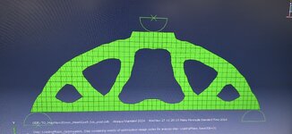
I have designed a 3 point bending test of a concrete beam and did topology optimization on it. Attached below is the result, I am generally satisfied with it but I have been trying to smoothen the sharp edges and introduce a symmetry about the middle (Left half design = Right half design) but can't seem to figure out how.

I thought of re-designing the problem as half the length and mirror the TO design afterwards. But am wondering if there is any geometric restriction that exist that I could use in Abaqus.

Would appreciate it if anyone could advice/help! Thank you in advance!Attachment_1728460714.jpeg
 
Replies continue below

Recommended for you

I don't think you can enforce symmetry. As to making it a more sensible shape that's where you come in, you define a shape that looks like the optimisied shape but satisfies your other requirements (smoothness, symmetry) then check the stresses again.
 
The best way of enforcing symmetry would be to create a half-model with BCs of symmetry.

Another key point to note: you say you are modelling a concrete beam (presumably reinforced concrete?) - but your results suggest the shape optimisation is based on an isotropic material, with tensile strength comparable to its compressive strength. In reinforced concrete, the tensile strength is developed in steel rebar, which is generally provided in straight lengths, and which requires detailing for anchorage, cover, etc. There is also the cost of formwork to consider.

There's a reason concrete load-bearing members are typically solid beams, rather than open trusses.
 
Tosca used by Abaqus in its Optimization module has symmetry available: Create Geometric Restriction --> Planar symmetry.
 
1) it doesn't look that asymmetric ... any asymmetry is probably due to roundoff (as I suspect the loading is symmetric).

2) I don't think you can model this with a symmetric BC ... how do you define the centerline BC (and end up with something like this ? Would you say "assume the upper and lower caps are effective for X" and the middle of the plate is ineffective ??

3) You want something more "sensible" ... ok, draft a "sensible" shape over this "ideal" shape. If you Really want to, figure out that your "sensible" shape is costing an extra 1% (2%?, 5%??) in weight, but saving you 50% of the machining time.

4) Have you done a meh convergence study on this ? run with 1/2 the grid size (double the number of elements)
 
The best way of enforcing symmetry would be to create a half-model with BCs of symmetry.

Another key point to note: you say you are modelling a concrete beam (presumably reinforced concrete?) - but your results suggest the shape optimisation is based on an isotropic material, with tensile strength comparable to its compressive strength. In reinforced concrete, the tensile strength is developed in steel rebar, which is generally provided in straight lengths, and which requires detailing for anchorage, cover, etc. There is also the cost of formwork to consider.

There's a reason concrete load-bearing members are typically solid beams, rather than open trusses.
Hey, great point there with the reinforced concrete! I’ve modelled this concrete beam as isotropic because I have tried adding the concrete damaged plasticity properties into the material & the stress analysis works fine but I kept getting aborted TO tasks & I couldnt decipher what is causing it.

This is actually just my research work to implement recycled aggregates into these TO PLA formwork, hence I forgo the reinforced bars as the FEM modelling would be very complex 😄
 
1) it doesn't look that asymmetric ... any asymmetry is probably due to roundoff (as I suspect the loading is symmetric).

2) I don't think you can model this with a symmetric BC ... how do you define the centerline BC (and end up with something like this ? Would you say "assume the upper and lower caps are effective for X" and the middle of the plate is ineffective ??

3) You want something more "sensible" ... ok, draft a "sensible" shape over this "ideal" shape. If you Really want to, figure out that your "sensible" shape is costing an extra 1% (2%?, 5%??) in weight, but saving you 50% of the machining time.

4) Have you done a meh convergence study on this ? run with 1/2 the grid size (double the number of elements)
Hey! Thanks for the response.
3. You are absolutely right! In fact, I’m comparing the time taken to print the formwork for this concrete beam & subsequently compare the strength/weight ratio of the beam compared to the others.

4) I have tried, currently I am using mesh size 5. But when I kept reducing the mesh size, I couldn't get a convergence. The stress at the contact point with the loading pin just kept rising and rising, I was baffled tbh. Any idea why this is happening? A few peeps on forum told me that it was somewhat similar to the hertz contact problem but I couldn’t figure out the problem
 
Thank you guys for the response, sorry for the very late reply, I wasn’t aware that there were replies.

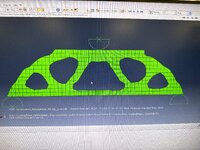
I just have an additional question, I was playing around the the TO parameters and I noticed that my TO tasks kept aborting stating that ‘success check string was not found in the solver output file’.

My parameters are as follows:
Objective Minimize SE, constraint <=30% volume fract. & max member thickness 30mm

I tried changing the volume constraint to 50% and max member thickness 20mm on different instances, both resulted with the same abortion. Any idea why this is happening? Any advices would be greatly appreciated!
EB3894F9-F98E-4782-AB5A-FB81EE2D901F.jpeg
 

Part and Inventory Search

Sponsor