Eng-Tips is the largest engineering community on the Internet

Intelligent Work Forums for Engineering Professionals

Torque on Wheel Studs 4

Status
Not open for further replies.

mjgarrin

Mechanical
Aug 5, 2015
13
0
0
US
Hello, there is probably a simple answer to this, but i have not been able to find it.

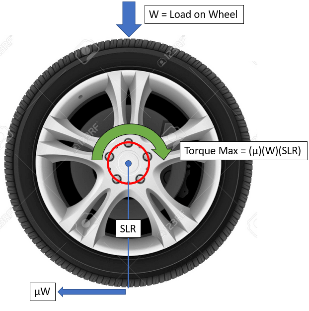
I am familiar with the idea that the max available torque from a wheel is dependent on the static load radius, load on the wheel, and the friction between the wheel and ground.

I am tying to determine the load path of this torque to the wheel studs. In the example picture, there are 5 wheel studs.
Wheel_Torque_Image_ctxvrq.png

Forces_on_Studs_lgqdfa.png

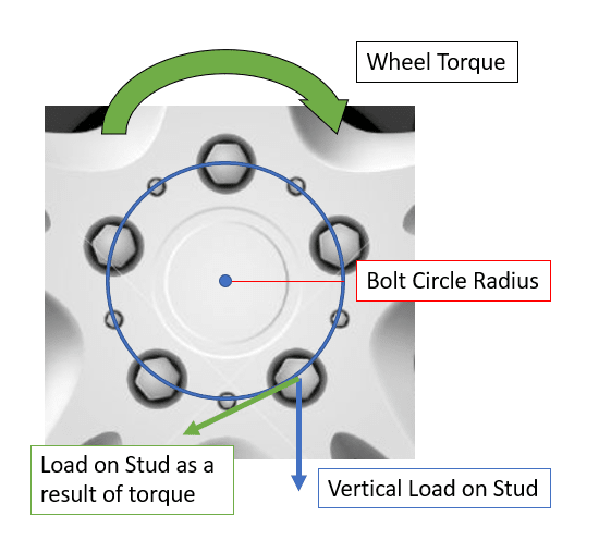
I know the studs see vertical loading evenly. So with 5 studs, each stud sees a vertical load equal to “W/5”.

Would the torque be distributed evenly between these 5 wheel studs?
If a take the bolt circle of the wheel studs, would dividing the wheel torque by the bolt circle radius determine the shear force acting on the wheel stud?
Or does a strong clamp load prevent the studs from seeing any torque or shear loading, and the torque is simply distributed to the hub?

Thanks!
Mike
 
Replies continue below

Recommended for you

The studs provide a strong clamping load and the friction between the hub and the wheel transmits the loads.

----------------------------------------

The Help for this program was created in Windows Help format, which depends on a feature that isn't included in this version of Windows.
 
Studs should not carry the weight of the vehicle to the tire. There is a shoulder on the hub that normally does this.

That can't be possible without an interference fit between the shoulder and wheel hole.

As already stated, the wheel is clamped to the hub so that friction between the two carries the vehicle weight and transmits the driving/braking torque.
 
Clearance on the pilot is probably around 0.005". That much movement in a stud with such a short length would fatigue it quickly.

Speaking of which, a question for the nut and bolt engineers, what do you call the length of bolt between the head and the threads where the tension is? Is there a name for the practice of extending the tensioned length by putting spacers and such in the system?
 
If the pilot or shoulder of the hub actually carried vehicle load then with the vehicle in motion it would be rolling against the wheel hole wearing out of both and quickly failing. It simply can't perform any purpose beyond holding the wheel until the nuts are tight.

TugboatEng - A while back I put a 0.008" between the wheel and hub on a later model Corvette and took a picture just to disprove a jackass that was claiming the car had interference fit wheels.
 
Tugboat - that extension is why people think split lockwashers work. Typically on sheetmetal, those otherwise useless lock washers extend the tension portion of the fastener sometimes double the original length.
 
Yup, best proof of a clamped connection for me was when I had the bolt and flange wear away on a drive shaft connection cause I forgot to torque one of the bolts. Hole and bolt badly worn, still good surface left on the flange though. I called a mechanic friend and he was like, 'new bolt, torque it and forget about it'. That connection outlasted the rest of the car.
 
TugboatEng said:
what do you call the length of bolt between the head and the threads where the tension is?

The term for this is 'grip length' - taken as the thickness of all clamped parts (including washers or spacers or whatever), or the measured distance between bolt head flange and nut flange when the fastener system is tightened.
 
Over the years Many cars and possibly some trucks have used "stud centric" wheel mounting, as opposed to the vastly superior "hub centric."

- Studebakers of the 50s and 60s.

- Honda Accord (4 lug) up to at least 1978, but more modern models are hub centric.

- International Harvester Scout 80A.

- Probably LOTS more.

Seems like five 1/2-20 nuts or bolt tightened to 90 lb-ft might exert about 10,000 clamping each, and provide enuff friction to hold a wheel immobilized against its hub in the presence of about 10,000 lbs of "shear force."
Others in this group know way better than me, but I'm guessing the ability of a pneumatic tire to deliver any meaningful radial shock load radially is pretty low, so the hub centering is great for proper centering the wheel/tire at installation, but probably hibernates until the next time the wheel is R&R-ed.
 
Hi TugBoat,

Were you replying to me ? In regards to the examples of stud centric vehicles?

I was working from memory on example 2, and was thinking of heading outside to take pictures of examples 1 and 3 ( plus, potentially a couple more) but chose to make a sandwich instead.

regards,

Dan T
 
"five 1/2-20 nuts or bolt tightened to 90 lb-ft might exert about 10,000 clamping each"

That's the way I'd look at it. Assuming mu is 0.3 that gives a factor of safety of 2 or so on the force required to rip the suspension out of the car and incidentally smash the wheel up completely in the square edge pothole test. Which is one of those fun tests we do, with a load cell in the pothole to measure the impact force.


Cheers

Greg Locock


New here? Try reading these, they might help FAQ731-376
 
Tmoose, yes that was for you. I was entertained by your comment. I wonder what life experience you've had that led you to retain such an obscure piece of knowledge. 3 generations of males in my family have lost a wheel while driving at high speed. Once in a Model A, a Morris Minor, and a Chevy K30.
 
A while back I put a 0.008" between the wheel and hub on a later model Corvette and took a picture just to disprove a jackass that was claiming the car had interference fit wheels.

To be fair, salty northern roads often create an interference fit between aluminum wheels and the steel shoulder. Its the main reason every decent tech or shop has a long handle 20'ish lb deadblow.
 
Status
Not open for further replies.
Back
Top