LL631
Industrial
- Nov 30, 2018
- 24
Hello,
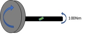
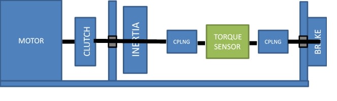
I am trying to assess the effect of inertia distribution on the reading from an In-line torque sensor in a small scale inertia dynamometer. As shown below the system has a rotary torque sensor with a brake attached to one end and an inertia mass on the other. The inertia is brought up to speed by the motor, the clutch decouples the motor, the brake is applied and the torque transducer measures the torque as the system is brought to rest. My head tells me that in this system the torque through the transducer(the measurement)is dependent on the distribution of inertia between the load-end & brake-end.
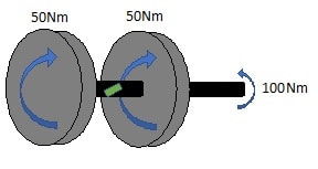
To simplify the system I treat all inertia on the load-end as one inertia mass (I2) & all inertia on the brake-end as another (I1), the shaft between the two represents the transducer. The transducer shaft and brake shaft have the same stiffness and 0 inertia. There is also no drag or play.
The brake torque causes the system (inertia) to decelerate: TB = I X a.
The inertia resists deceleration therefor creates a reaction torque: TB = TReaction
The total reaction is the sum of the individual parts: Tb= T1+ T2.
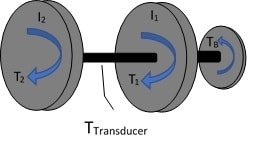
It is then obvious that the torque measured over the transducer is TB - T1.
Is this theory correct? I know the situation is very simplified, I just need enough proof to argue the point against using this equipment setup.
Cheers
I am trying to assess the effect of inertia distribution on the reading from an In-line torque sensor in a small scale inertia dynamometer. As shown below the system has a rotary torque sensor with a brake attached to one end and an inertia mass on the other. The inertia is brought up to speed by the motor, the clutch decouples the motor, the brake is applied and the torque transducer measures the torque as the system is brought to rest. My head tells me that in this system the torque through the transducer(the measurement)is dependent on the distribution of inertia between the load-end & brake-end.
To simplify the system I treat all inertia on the load-end as one inertia mass (I2) & all inertia on the brake-end as another (I1), the shaft between the two represents the transducer. The transducer shaft and brake shaft have the same stiffness and 0 inertia. There is also no drag or play.
The brake torque causes the system (inertia) to decelerate: TB = I X a.
The inertia resists deceleration therefor creates a reaction torque: TB = TReaction
The total reaction is the sum of the individual parts: Tb= T1+ T2.
It is then obvious that the torque measured over the transducer is TB - T1.
Is this theory correct? I know the situation is very simplified, I just need enough proof to argue the point against using this equipment setup.
Cheers