Continue to Site

Eng-Tips is the largest engineering community on the Internet

Intelligent Work Forums for Engineering Professionals

  • Congratulations KootK on being selected by the Eng-Tips community for having the most helpful posts in the forums last week. Way to Go!

Torsion capcaity of a Fin or shear tab steel connection with top flange connected

Status
Not open for further replies.

allimuthug

Civil/Environmental
Oct 5, 2014
142
Hi
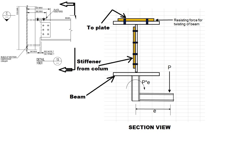
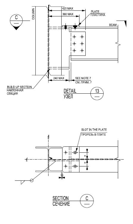
I have a shear tab connection of HE400 A (European Section) longitudinal beam with HE300 A column as shown below.
Shear_Tab_Connection_bocdkb.jpg


The cross looks like this
Shear_tab_connection_ross_section_view_jeyb26.jpg


When some pipe supports are supported on the longitudinal beam, as shown the picture above shall cause torsion on the beam.
The beam is restrained by the bolts on the web and top flange. Please explain me how to find the torsional capacity on the beam.
 
Replies continue below

Recommended for you

Please explain me how to find the torsional capacity on the beam.

In my opinion, you'd have virtually none because the bottom flange of the beam is not restrained. Ergo the torque will get to the "stiffener" by bending in the web (which likely doesn't have much capacity). If you restrained the bottom flange as well.....you might be in business.
 
It means the T beam doesn't have any torsional capacity. I can understand that the couple is formed from the web and the flange.
What does the top flange do in this case?
 
A T-beam does have torsional capacity......but you've got this thing welded (if I understand this pic correctly) to the bottom flange of a I-Beam.

In the case of no restraint of either flange.....we've discussed this before (on the board):


Note my diagram in the thread. You'd have half of that situation here.....but it would still be enough to put the web (above the bottom flange) in bending. (Which would likely fail it for any significant load.)
 
Status
Not open for further replies.

Part and Inventory Search

Sponsor