Continue to Site

Eng-Tips is the largest engineering community on the Internet

Intelligent Work Forums for Engineering Professionals

  • Congratulations cowski on being selected by the Eng-Tips community for having the most helpful posts in the forums last week. Way to Go!

Torsion in I beams 1

Status
Not open for further replies.

bangerjoe

Industrial
Oct 16, 2013
35
hello
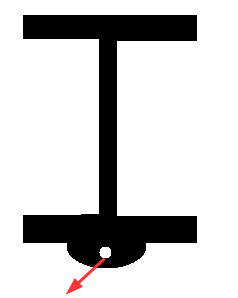
I have a lug on a beam loaded at a fleet angle.
this may be a very elementary question but am i ok to check for biaxial bending.

can't find any standards/examples that use torsion and biaxial bending.

parpadelle_dq7vo4.png


Thanks for any help
 
Replies continue below

Recommended for you

The torsion check is definitely required. There's a handy shortcut that I'd recommend that you can use to transform torsion into just extra weak axis bending. Search for "bi-moment method + torsion", either here or using Google.

I like to debate structural engineering theory -- a lot. If I challenge you on something, know that I'm doing so because I respect your opinion enough to either change it or adopt it.
 
Hi KootK.

I've googled such a thing and am working through reference i found Here:


i'm sorry to drag you into mathematics, but an equation calls for phi''. presumably the rate of change of the rate of change of the angle of twist.

i'm having no luck locating a suitable reference for finding formulae for phi ''. phi (angle of twist) is elementary.

Are you experienced with this?

Regards, Joe
 
Happy to help. The equation for phi is equation number one on the second page of the document that you linked. This is an excellent reference for torsion of you intend to use the rigorous approach: Link

I like to debate structural engineering theory -- a lot. If I challenge you on something, know that I'm doing so because I respect your opinion enough to either change it or adopt it.
 
THanks KootK,

I'm trying to derive the σ_w which is give by -E.W_nwfs.Φ''.

The 'phi prime prime' is giving me a headache. trying to get its value at the point of loading of my lug.

thanks for you reference, I'll have a look!

 
Joe -- You may have already considered this, but make sure to take into account the support conditions of your beam. If the flanges aren't restrained, you won't develop the σ_w stresses.

I'd second the reference KootK linked -- has all the detail you'll need for a fully rigorous solution, and I believe it also outlines the shortcuts you can take when being fully rigorous isn't required.
 
Rather than getting into a full torsional warping, I often point folks towards the Equivalent Tee method.

Essentially, you treat the torsion as a force couple applied to the top and bottom flanges of the I beam. Then analyze the tee beam to take the weak axis moment from that load.

It's simple in concept, it's conservative and it allows you to conceptually understand what those warping torsional stresses are really doing to your beam.

Nothing wrong with doing a full torsional warping calc with Phi and integrations and charts and such. But, if you lose the conceptual understanding and look at the issue instead as a exercise in mathematics, then I think you have lost something.
 
Lomarandil -

Yes, the flange restraint does matter. But, you'll still get warping stresses.... they just won't be at the unrestrained ends of the beam. Since they're not at the ends of the beams where (presumably) the maximum moments occur, they are less likely to control the design. But, it is still possible for warping + bending to control at the mid-point of the beam.
 
You should check AISC H3 (13th ed...not sure about 14th) for design checks. If you want to go real deep into it the torsion will add additional shear stresses at the extremities of the beam's cross-section. AISC has a design manual with lots of fun charts developed from diff. equations for different torsional fixity conditions allowing you to determine the shear stress based on J, G, maybe Cw, etc. I can't recall the design guide # but I think there's a free pdf online. I've had to go through the process for channel stringers and HSS perimeter beams where handrails were welded onto them thus cranking in torsion--which is a pretty common problem.

Also I think RISA can at least do the AISC H3 design check if you simply want to model it and move on.
 
Hi everyone,

Thanks for your replies.

I will look into the equivalent T method. Thanks JoshPlum

might be asking some more questions if I get confused!

It is nice to have such a supportive community out there :)

 
So, JoshPlum, I googled the topic of equivalent T, first result was a link to this forum, where you give a procedure.

1) For torsion, think of the I beam as having been split at the center. Hence forming two Tee beams.

2) If the original beam was warping restrained at the ends, then your tee beam will be a fixed-fixed beam. If your original beam did NOT restrain warping, then your tee beams will be simply supported.

3) Break your torsional load into a force couple applied at the centroid of the Tee. Apply these point load or distributed load to each tee beam individually and analyze using simple beam theory.

4) The simple beam theory will develop weak axis bending moments (and flange bending stresses) in the Tee that are similar to the warping stresses that you'd get from a more rigorous analysis.


I have some questions if you don't mind:

My loading case will give me a Mx and and My as well as this torsion from the eccentricity.

Do I combine my Mx and My stresses from the loading case (considering the whole beam), then add them to the weak axis moment on the tee section?

not wanting to sound juvenile, I would love a worked example!

Regards,

Joe

 
I've had a situation where a small degree (4 degrees) of radial deflection caused a 10 inch deflection on the end of the beam (which was a pipe support). If deflection is a parameter then you want to eliminate most of the torsion.
 
Joe -

I don't think I have a worked example. What you do after you have an estimate of the warping stresses is a bit of an engineering judgment. But, at least you have some good theoretical understanding of what these stresses are and what their magnitudes will be.

Some folks will use AISC chapter H3.3. But, the problem with that section (IMHO) is that even a very small torsion immediately reduces the capacity of your section. That may work for a member that is primarily in torsion, but for a member that is primarily in bending it is problematic.

I prefer to use the following procedure (which I believe comes from Design Guide 9, though I can't remember exactly where. Convert the warping stresses into an equivalent weak axis moment that would produce the same extreme fiber stresses. This equivalent moment then gets added to your actual weak axis moment (since they produce the same sort of stresses). Then you use your regular chapter H equations for combing axial force, strong and weak axis moments to get a code check for the section.

There is also a shear stress aspect of it that should be checked as someone else already noted.

Someone mentioned that RISA checks WF for torsion and that's true. However, there are limitations and assumptions to RISA's treatment. It may be better than what the other guys are doing (STAAD, SAP, RAM), but RISA does have some limitations with warping. 1) RISA only considers warping stresses for beams with fixed ends (i.e. moment connections), 2) The fixed ends are always considered "torsionally fixed", so the solution may not be 100% accurate for a "torsional pinned" moment connection. 3) The stresses are calculated for loading consisten with DG-9 case 2, which is a constant torque.

My belief is that RISA's results will usually be conservative (which is why we chose the limitations the way we did). But, they are only exact for certain situations. So, I always encourage users to run their own simplified (i.e. equivalent Tee) hand calcs when torsion can be considered a significant design criteria for their beam.
 
I have typically used STAAD (which is based on AISC's design Guide 9; at least the last time I used it). I have some spreadsheets as well.

Be aware that normal (end) connections will likely not suffice. If you are using simple shear connections at the ends (i.e. torsionally "pinned"): you will wind up with too much stress in the web to transfer it to the connection. (I did a study on this some years back.) You typically need some type of flange restrained connection (i.e. moment; torsionally "fixed") to transfer a significant amount of torque (unless you have some intermediate/sub framing that won't let it get to the ends).
 
WARose,
If your end connections are "pinned" / simple shear connections (for vertical shear/beam reaction), what torsional stresses are you trying to transfer into the connection?
If its torsionally pinned, torsion should be zero at the ends and the interior of the beam will resist any additional torsion that would have otherwise been taken out at the flange restraints.
 
WARose -

I'm going a bit off topic here.... So, others feel free to move on.

I agree that a clip angle connection would be torsionally pinned and that it would likely not work for significant torsions. However, my impression has always been that a standard fixed moment connection (bolted end plate or flange plate moment connection) is closer to a torsionally pinned connection than a torsionally fixed connection.

The idea is that the flanges of the WF column are very restrained against twist. Not unless you have continuity plates or "side plates" or some other stiffening mechanism.

The reality is that all moment connections are somewhere between torsionally pinned and torsionally fixed. This is one of the problems that I have with "rigorous" methods. There really isn't a way to handle these intermediate cases. That's why I like the equivalent tee method. You can model a "spring" moment restraint at the end of your beam to give you partial fixity. That way you get results between the idealized fixed and idealized pinned situations.
 
If your end connections are "pinned" / simple shear connections (for vertical shear/beam reaction), what torsional stresses are you trying to transfer into the connection?
If its torsionally pinned, torsion should be zero at the ends and the interior of the beam will resist any additional torsion that would have otherwise been taken out at the flange restraints.

The torsion can be resolved to forces that try to get out of the beam (at the ends) by forces that are perpendicular to the normal shear in a beam (they act against the clip angles like a seated beam connection; but you have to get them there first and that induces bending in the web which kills it 9 times out of 10). I studied this problem extensively one time (after failing to find anything in the literature that takes on the topic of clip angles in a torsionally loaded beam situation). I even went so far as to model a I-Beam (completely) with plate elements.
 
I agree that a clip angle connection would be torsionally pinned and that it would likely not work for significant torsions. However, my impression has always been that a standard fixed moment connection (bolted end plate or flange plate moment connection) is closer to a torsionally pinned connection than a torsionally fixed connection.

The idea is that the flanges of the WF column are very restrained against twist. Not unless you have continuity plates or "side plates" or some other stiffening mechanism.

The reality is that all moment connections are somewhere between torsionally pinned and torsionally fixed.

Excellent points. And something else to remember along those lines is: the rotational estimate you will get out of these programs will be (like you said) based on the beam being perfectly pinned or fixed......and as you said: it's neither. So its best to check it both ways and go with the worst case scenario.
 
In my opinion, the cases that warrant consideration as torsionally fixed are few and far between. Similar to Josh's list:

1) Flange continuity / load symmetry.

2) Side plating and other intentional attempts at fixity.

3) Serious encasement in concrete.

True torsional fixity creates monstrous demands for support stiffness. In most cases, assuming torsional pin-ed-ness (sp?) is a pretty safe bet.

I believe that Josh's Equivalent Tee method and my Bi-Moment method are one and the same. "Bi-moment method" seem to be more Googlable. I'm making up words all over the place. Basically, just follow the info pasted below, clipped from the AISC design guide that I linked above.

JoshPlum or BangerJoe said:
Break your torsional load into a force couple applied at the centroid of the Tee.

I believe that the most theoretically correct locations for the force couple components are the Tee shear centers. Of course the shear centers, centroids, an top of top flanges (pic below) are more or less all at the same location for Tees. Using the centriod produces the most conservative result which, perhaps, is why you've taken that tack.

Capture_1_lrdsnm.png


Capture_02_nqpveg.png


I like to debate structural engineering theory -- a lot. If I challenge you on something, know that I'm doing so because I respect your opinion enough to either change it or adopt it.
 
Status
Not open for further replies.

Part and Inventory Search

Sponsor