Eng-Tips is the largest engineering community on the Internet

Intelligent Work Forums for Engineering Professionals

torsion - measuring deflection in radians

Status
Not open for further replies.

NorthCivil

Civil/Environmental
Nov 13, 2012
555
0
0
NZ
I've got a weird one that i know i could have solved in my university days, but has me scratching my head these days.

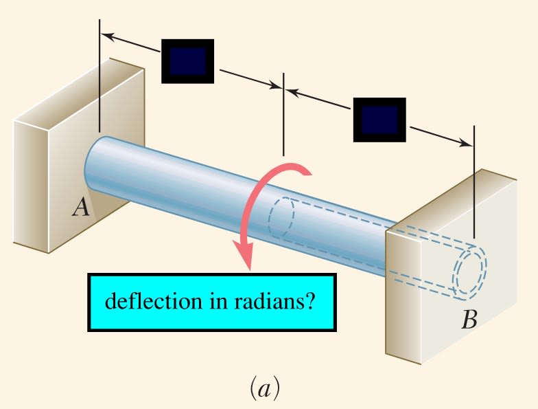
I have a column, fully fixed at both ends, very tall (~9metres)

It is subject to near nil compressive forces, or bending forces (no WL2/8 business). but it is very tall, ideally slender, and subject to a rotational load (from a big piece of signage which will me mounted off of the side, cantilevered out ~2 ft or so.)

the rotational force upon it will be quite large.

I am having trouble checking the column for rotational deflection. i have my old mechanics of materials textbooks out, but they are going deep into differential equations to solve, and don't have this particular case solved.

there must be some way to express/calculate the deflection in radians?

the idea is this sign shouldnt be flapping back and forth too much in the wind.

Screenshot_2024-08-21_140811_a2aj0a.jpg
 
Replies continue below

Recommended for you

Do you have 'Roark's Formulas for Stress and Strain'? He has a lot of formulas for it.

If we are talking about a circular cross section, the formula is:

Φ=TL/JG

Where:
Φ= rotation [in radians]
T=applied torque
L=Length
J=Polar moment of inertia
G=Shear modulus
 
yeah, that is so easily missed. draw the FBD ... the torque is reacted at both ends.

tension, axial, loads cause axial strain/deflection. Torque causes rotational deflections.

"Hoffen wir mal, dass alles gut geht !"
General Paulus, Nov 1942, outside Stalingrad after the launch of Operation Uranus.
 
Salmon and Johnson, or the newer Salmon, Johnson, and Malhas has a great chapter on torsion. It's a lot easier to follow than what you'd find in an Advanced Mechanics of Materials or similar textbook. You might check that out.

I started to point you to the AISC Design Guide 9, but it's so focused on open shapes that it's not a lot of help for this. If you wanted the stresses, then it shows how to compute those. There are pages of graphs near the end of DG9. I'm not sure if those apply to closed shapes.
 
Thanks everyone for your replies

i've gone through a handful of resources - Rourkes, AISC, some miscellaneous papers... it appears there is no standard method...

ive got a few different spreadsheets set up and i will run an FEA and see how everything compares.

thanks for your time and the referrals to past threads.
 
Isn't what WARose wrote a standard method. If the shaft properties change where the torque is applied then the stiffness of the torsion springs in parallel where

(Φ/T)[sub]1[/sub] = L[sub]1[/sub]/J[sub]1[/sub]G = K[sub]1[/sub]
(Φ/T)[sub]2[/sub] = L[sub]2[/sub]/J[sub]2[/sub]G = K[sub]2[/sub]

and the combination is

1/(Φ/T) = 1/K = 1/K[sub]1[/sub] + 1/K[sub]2[/sub]

used as

Φ = T * K
 
hi 3DDave yes this method is the simplest.

Though is appropriate for "cantilevered" members with a torque on the end, rather than torque on an element with both ends fixed.

a member with both ends fixed will rotate much less - this phenomenon seems to have a range of proposed equations that describes it
 
You are looking at the addition of both segments, each separately fixed at the ends and set to the same angle in the middle, which is what the above equations are describing.

If you have other solutions then what are they?

Are you concerned that there is enough deformation that the infinitely rigidly mounted ends, which you installation won't have, are drawn together and add to the force required?
 
If both ends are fixed and the torque is applied at midspan, half goes to each end and the torque is constant over the span, namely Mt/2.

The total twist at midspan is phi = theta*L/2 = Mt*L/(4G*Ip)
(Reference Timoshenko & McCullough Elements of strength of Materials):

where L is span between fixed ends, Mt is applied torsional moment at midspan, G is shear modulus and Ip is polar moment of inertia of the shaft.

 
I thought that the column in the original post was a constant section.

If torsional stiffness is symmetrical over the span, and the moment is applied at midspan, each fixed end would still resist half of Mt.

If torsional stiffness is not symmetrical , or Mt is applied eccentric to midspan, Mt would not be evenly divided between supports and variable torsional rotation would need to be considered.


Status
Not open for further replies.
Back
Top