MegaStructures
Structural
- Sep 26, 2019
- 376
Hello:
I am designing a small frame with significant torsion applied to some members in RISA3D. After going through the help manual I have found that RISA does not account for any torsion in beams, besides torsion caused by frame racking (fixed end condition, point torques at ends), similar to what is found in case 2 of AISC DG9. Of course this means I cannot trust the results from RISA and I need to input my own torsional stresses, so I have set out to figure out how to do the hand calc.
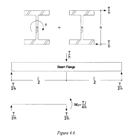
I reviewed some threads here on the forum and see some users suggesting the "equivalent tee" or "bi-moment" method to conservatively approximate the shear and normal stresses from torsional warping as suggested in AISC DG 4.1.4. The DG provides the figure below and says the normal stresses can be found by treating each flange as a beam and using the following equation σw= Mf/Sf where; Sf= (tf*(bf)2)/6. I assume the flange in the figure below (fig 4.4) is showing the side view of the entire length of the beam.
So, to me this method seems extremely simple and if accurate and conservative I am happy to have found it, because it will take me only minutes to check my beam. I do have a couple questions though and as I am typing this I realize this post might even be more suited for the RISA sub.
1) Is this method accurate enough (conservative is probably a better word) and at what unity ratio from pure torsion should I opt for a more accurate calculation of torsion stresses i.e. if torsion capacity calculated per this simplified method is 50% of the beams flexural capacity, but the beam still passes code checks should I be worried?
2) If this method is so simple and seemingly well suited for an automated calculation, why in the world does RISA not support it as a simple check? The fact that they don't makes me feel like I'm missing something about the usefulness of this method
3) In this review I have looked more at how RISA combines torsion stresses in the interaction equation and it combines torsional warping stress with weak axis moment, which seems to contradict what DG9 is suggesting, since the torsional warping moment found in the equation above is a stress normal to the flanges, or a major axis moment. How can this discrepancy be explained?


**As a bonus question has anyone used a shell element model to study the effects of torsion on I-beams that can speak on the efficacy of that method? I have created an FEA model of my frame with shell elements, the beams are relatively short < 10 ft W21x76's and support a point torque of 48 kip*ft and won't be limited by LTB and I'm not aware of any other buckling modes I need to be aware of (pure torsional buckling in the web?). I have ran a linear-static model and show very favorable stress results, which I am trying to confirm with this hand calc and of course the original RISA results.**
I am designing a small frame with significant torsion applied to some members in RISA3D. After going through the help manual I have found that RISA does not account for any torsion in beams, besides torsion caused by frame racking (fixed end condition, point torques at ends), similar to what is found in case 2 of AISC DG9. Of course this means I cannot trust the results from RISA and I need to input my own torsional stresses, so I have set out to figure out how to do the hand calc.
I reviewed some threads here on the forum and see some users suggesting the "equivalent tee" or "bi-moment" method to conservatively approximate the shear and normal stresses from torsional warping as suggested in AISC DG 4.1.4. The DG provides the figure below and says the normal stresses can be found by treating each flange as a beam and using the following equation σw= Mf/Sf where; Sf= (tf*(bf)2)/6. I assume the flange in the figure below (fig 4.4) is showing the side view of the entire length of the beam.
So, to me this method seems extremely simple and if accurate and conservative I am happy to have found it, because it will take me only minutes to check my beam. I do have a couple questions though and as I am typing this I realize this post might even be more suited for the RISA sub.
1) Is this method accurate enough (conservative is probably a better word) and at what unity ratio from pure torsion should I opt for a more accurate calculation of torsion stresses i.e. if torsion capacity calculated per this simplified method is 50% of the beams flexural capacity, but the beam still passes code checks should I be worried?
2) If this method is so simple and seemingly well suited for an automated calculation, why in the world does RISA not support it as a simple check? The fact that they don't makes me feel like I'm missing something about the usefulness of this method
3) In this review I have looked more at how RISA combines torsion stresses in the interaction equation and it combines torsional warping stress with weak axis moment, which seems to contradict what DG9 is suggesting, since the torsional warping moment found in the equation above is a stress normal to the flanges, or a major axis moment. How can this discrepancy be explained?


**As a bonus question has anyone used a shell element model to study the effects of torsion on I-beams that can speak on the efficacy of that method? I have created an FEA model of my frame with shell elements, the beams are relatively short < 10 ft W21x76's and support a point torque of 48 kip*ft and won't be limited by LTB and I'm not aware of any other buckling modes I need to be aware of (pure torsional buckling in the web?). I have ran a linear-static model and show very favorable stress results, which I am trying to confirm with this hand calc and of course the original RISA results.**


