Continue to Site

Eng-Tips is the largest engineering community on the Internet

Intelligent Work Forums for Engineering Professionals

  • Congratulations KootK on being selected by the Eng-Tips community for having the most helpful posts in the forums last week. Way to Go!

Torsion on bar which is not fixed?

Status
Not open for further replies.

PCarson85

Mechanical
Jul 8, 2017
7
I am trying to solve for maximum shear stress on a notched round bar being driven by a direct drive motor giving torque T which is also machining something with a force F as shown below.
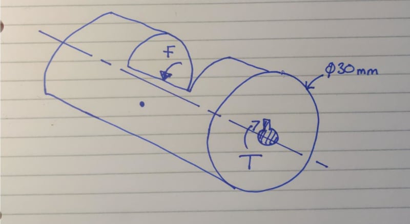
Scan_-_2020-02-08_20_15_47_au8yat.jpg

22_tel7x4.png


Max shear stress where Ip = polar moment of inertia of the cross section with respect to the center
R is radius
T is Torque


Text book examples seem to assume a fixed end when calculating shear stress... how can we calculate the torque increase when a force is applied in the opposite direction of the motor?
 
Replies continue below

Recommended for you

You need to draw an FBD that is in equilibrium before you can decide that. T=F*15mm? in that case you need to add at least one more force. How is t generated, acorss the entire face, at the keyway,(ug) or at the shaft by friction?


Cheers

Greg Locock


New here? Try reading these, they might help FAQ731-376
 
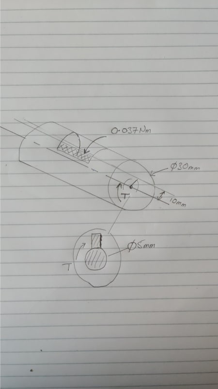
So I've drawn a little more detail below from what I know. The torque acting against the shaft will be 0.037Nm which is 10mm radius away from the center of the shaft.

The shaft will have a key which will transmit the power from a motor to the shaft to rotate.

The shaded area in the shaft will be a pencil sharpener fixed into position, this is what is causing the resisting torque by sharpening a pencil.

The shaft will be held in place by two bearings.

For the torque on the motor, I am thinking that it has to overcome the resisting torque by the pencil sharpener, as well as the inertia of the shaft itself and any friction caused by the bearings. For the inertia of the shaft, I will need to see what the minimum shear stress allowable is, so I can choose the correct material which will give me the weight.

Scan_-_2020-02-09_11_36_26_llzu88.jpg
 
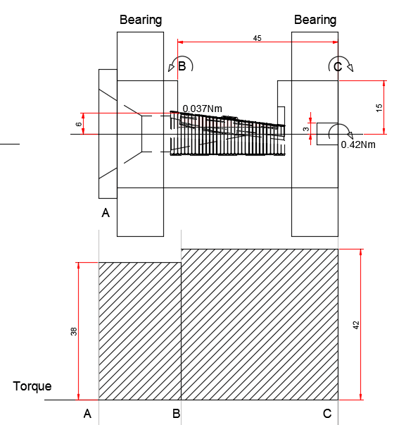
For clarity I've tried to clear up the problem by producing a free body diagram as shown below, does this look correct?

T1_uydxht.png


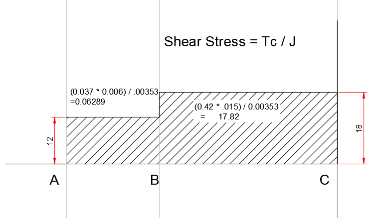
T2_sbttdw.png
 
The aproximate answer is to assume the shaft as fixed to the motor with torque applied at the coupling or other interface to the load.


Looks like the tapered CSK is where the pencil goes in. In this problem you will have a stress concentration at the key. As the key depth looks to be a large % of the diameter. There are charts for these values, but the ratio of slot depth to shaft diameter looks very high here.
 
Status
Not open for further replies.

Part and Inventory Search

Sponsor