Continue to Site

Eng-Tips is the largest engineering community on the Internet

Intelligent Work Forums for Engineering Professionals

  • Congratulations waross on being selected by the Eng-Tips community for having the most helpful posts in the forums last week. Way to Go!

Torsion on HSS with slotted shear tabs on both ends

Status
Not open for further replies.

STpipe

Structural
Apr 29, 2010
153
Hey all,

I'm currently performing a review on design calculations submitted to us and one of the HSS beams in the structure has two point loads with an eccentricity to the beam's centroid. The connection of the beams to the columns is achieved using a plate slotted through the HSS and bolted to shear tabs that are welded on the column. This seems like a bad design and I'm not even sure how to even begin quantifying the torsional resistance of the connection. Is this simply a case where the connection detail needs to be changed?
 
Replies continue below

Recommended for you

STpipe said:
Is this simply a case where the connection detail needs to be changed?
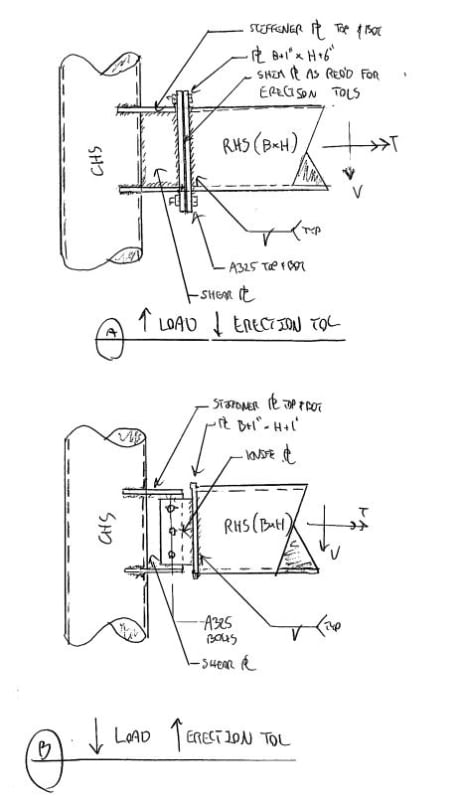
Quite possibly. I might let that go for small loads but not for anything serious.

You can evaluate the capacity by envisioning the plates high and low horizontal strips forming weak axis loaded cantilever beams. The resistance of each "beam" multiplied by the distance between them becomes a couple representing torsion capacity. It's still mostly crap though. And the effort involved is usually enough to motivate most folks to just detail it better to begin with.
 
I'd have to see a pic to make sure I'm understanding this.....but it sounds to me like it can transfer some torsion.
 
The connection you described is for axial or direct shear loads, not torsion. If the loads are significant, I would change the connection to an end plate.
 
Thanks for all the responses!

Quite possibly. I might let that go for small loads but not for anything serious.

You can evaluate the capacity by envisioning the plates high and low horizontal strips forming weak axis loaded cantilever beams. The resistance of each "beam" multiplied by the distance between them becomes a couple representing torsion capacity. It's still mostly crap though. And the effort involved is usually enough to motivate most folks to just detail it better to begin with.

KootK,

Define "small loads". Right now, I'm estimating the torsion at each end would be equal to ~0.9 kips ft.

I'd have to see a pic to make sure I'm understanding this.....but it sounds to me like it can transfer some torsion.

WARose,

I attached a crude sketch of the problem. One thing I neglected to mention is that the shear tabs are detailed with stiffeners on them. I imagine there is some ability to transfer torsion, the question is how much and how to quantify that amount.

The connection you described is for axial or direct shear loads, not torsion. If the loads are significant, I would change the connection to an end plate.

hokie66,

That's typically the assumption I would make. Ideally the source of torsion should be eliminated altogether or the connection modified as you describe.
 
 https://files.engineering.com/getfile.aspx?folder=0c8a73f2-dd78-45f5-b76b-9802c1c756e2&file=Sketch.pdf
I attached a crude sketch of the problem. One thing I neglected to mention is that the shear tabs are detailed with stiffeners on them. I imagine there is some ability to transfer torsion, the question is how much and how to quantify that amount.

Looks to me like it can transfer some. I don't see the slot for the bolt holes you were talking about (i.e. is it vertical or horiz.?).

Just a matter of grinding the numbers and seeing what you get. (Including a rotational stiffness estimate for the connection.)

Bending of that plate (that connects the tab to the HSS) will likely be the weak link.

 
The slot I mentioned referred to the slotted connection of the plate to the HSS which then connects to the shear tab on the column.

I looked through AISC's design guide on torsion, but couldn't find relevant information on my case. This to me indicates that detailing this connection is more trouble than it's worth. Entertaining the idea of keeping the detail as is, I see three steps in validating the connection.

1) Checking the welds to see whether they can transfer the force to the connection plate in the HSS.
2) Checking the torsional capacity of the plate
3) Checking whether the weld group that connects the shear tab + stiffeners can transfer the torsion.

I'm not even sure how I would approach item #1. The other two shouldn't be too hard and I can probably dig up the information from one of my books.
 
Not sure what the mid-depth stiffener is supposed to do. Perhaps if that were top and bottom...
 
Torsion aside, this really isnt a great connection for transmitting shear. More of an axial load setup.

Agree with hokie on the stiffener location. It's positioned for minimum efficacy.
 
Any chance this beam's primary function is that of a wind girt?
 
Stpipe:
Why not use two vert. shear tabs, one on each side of the column? These could be located on the column so that the HSS beam would slip down btwn. the two shear tabs. The HSS beam would be cut several inches short of the col. so you could have access inside the beam. Now, the tabs are truly separated for a good moment arm to take the torsion and they are also oriented in a stronger direction, as KootK wished he had “plates high and low horizontal strips forming weak axis loaded cantilever beams…..” The webs of the HSS would be drilled for bolts to the shear tabs and the nuts/bolts might be one of the concealed nut type bolt systems. The shear tab stiffeners are no longer needed because the shear tab loads are already applied out near the radius’ of the column instead of at its center axis. The exact details would be a function of the loads and member sizes.
 
KootK,

I'm 100% sure it's not a wind girt.

dhengr,

Thanks for the suggestion. However with implementing this, wouldn't the column and beam have to be relatively the same size? My sketch was not exactly to scale so I don't think it might work. And if I'm going through the trouble of changing the connection detail, an end plate detail would probably be the best option.
 
OP said:
Define "small loads".

I'd have to put you in touch with my lawyer for that. Every man for himself.

c01_ubwlqb.jpg
 
KootK

Thanks for the sketches. Based on my particular problem, I think option B could be implemented. If I understand the load transfer mechanism, it would go as follows:

The torsion goes to the knife plate which transfers the load to the connection at the column via the bolts through tension at the top bolt and compression at the bottom bolt. The top and bottom stiffener plates welded to the CHS would form a couple that resist the torsion through shear and transfers it as a moment to the column.

The only issue I have with the detail, is that how is it different than the original? Do I not have the same issue with the knife plate as I did with the shear tab in the original detail in that it's not the greatest cross-section to transfer torsion?

 
Yes, that is what KootK means by not much load, but good for erection.
 
Shouldnt option B also have stiffeners on other plate?
Maybe one sided stiffeners on both,like back to back channels.
 
STpipe said:
Thanks for the sketches. Based on my particular problem, I think option B could be implemented.

You're most welcome STpipe. Any chance you'd be willing to tell us what your particular problem is? Application and member sizes would both be helpful.

STpipe said:
If I understand the load transfer mechanism

You understand it as I do.

STpipe said:
The only issue I have with the detail, is that how is it different than the original? Do I not have the same issue with the knife plate as I did with the shear tab in the original detail in that it's not the greatest cross-section to transfer torsion?

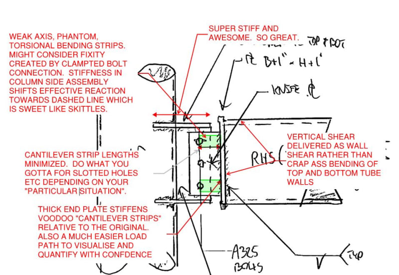
Were they to be laboratory tested, I'm confident that my detail B would prove considerably stiffer than your originally posted detail. The key, I think, is to examine the original detail for sources of significant flexibility. Those sources of flexibility will become the undesirable features of the connection. Next, examine my detail "B" and consider where things have been improved.

STpipe said:
Define "small loads".

Fiiiiiinnnnne... YOUR load is small. This will work at reasonable plate thicknesses. Of course, I'm making reasonable assumptions about your member sizes on account of my not knowing them.

c01_sbemzi.jpg
 
kiltor said:
Shouldnt option B also have stiffeners on other plate?

Stiffeners would make it stronger and stiffer, obviously, but I'm confident that the unstiffenened version would be sufficient for the modest load contemplated here.

kiltor said:
Maybe one sided stiffeners on both,like back to back channels.

Swapping out the knife plate for a short length of channel would be stiff and cheap if the member depths would make sense for that. Room for a C8 etc.
 
Probably cheaper to cut out the fourth wall of the RHS than to weld a channel on the end.
 
Agree with Kootk's "bending strips" in his pic. (If I understand him correctly.) In the thread below, I sketch out how torsion runs out in a connection like this. The torsion doesn't get out of the knife plate by pure shear stresses.....there is out-of-plane bending to consider.

 
Status
Not open for further replies.

Part and Inventory Search

Sponsor