Eng-Tips is the largest engineering community on the Internet

Intelligent Work Forums for Engineering Professionals

Torsion spring - arm angle ???

Status
Not open for further replies.

VPOW

Mechanical
Feb 8, 2021
5
0
0
AU
hi there,

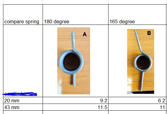
I have attached two torsion spring image. My understanding, to get optimum spring force from the torsion spring, the angle between the spring arm is critical. I have spoken to spring a manufacture however not very helpful but i got confused. Apparent, it is not the long arm that determine the between the spring angle. Im totally confused. Any spring expert out there that can advise. Can anyone tell me what is the best way to determine the spring
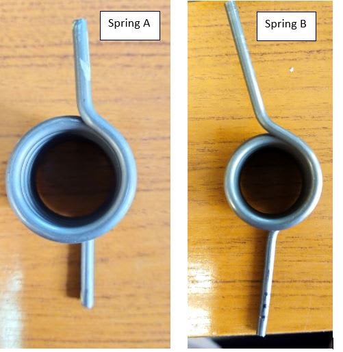
Spring_A_B_zi3z4q.jpg
arm?
 
Replies continue below

Recommended for you

There’s nothing to see when you click the attachment can you post a picture of the spring

“Do not worry about your problems with mathematics, I assure you mine are far greater.” Albert Einstein
 
Please don't use the ampersand (&) character in file names that you upload; engineering.com doesn't handle them correctly.
 
Hi there

Have a look at this web page it may help

I am not sure from your post exactly what you are asking but when you design a torsion spring it basically needs two positions; the first position is the preloaded position where the spring is assembled in place and the second position is the final load position where the spring as been loaded during operation.

“Do not worry about your problems with mathematics, I assure you mine are far greater.” Albert Einstein
 
Hi there,

The specification of both spring are the identical apart from the spring arm. Hence when we conducted spring load test. As shown in the image below.
Spring A has more spring clamping force on 20mm object as compare to spring B. Both are installed on the same spring clamp housing. Just try to understand.

Compare_spring_tuhf65.jpg
 
Hi again

First are the numbers 9.2, 6.2, 11, 11.5 are they the forces? What is the 43?
You need to be clear with the information and also why does spring A look physically different to spring B.
A change in geometry might well alter the spring rate but if the 11 and the 11.5 are forces in a certain position that’s pretty good, although the 6.2 and 9.2 are a bit adrift assuming they are forces.
If the physical dimensions of the spring are different then different forces will be obtained for the same given angle of the torsion spring.
Any spring will vary from one to another because of tolerances in wire diameter, outer/inner diameter of spring, also if the angles of the spring arms are different from one spring to another then that will also change the forces.


“Do not worry about your problems with mathematics, I assure you mine are far greater.” Albert Einstein
 
hi there,

Thank you for your reply.

These are the test result. We used force gauge to determine how much force it required for the clamping jaw to open when clamping a 20mm/43mm object. Hence 9.2, 6.2 ,11 and 11.5 are the force.

Both spring are identical ie the OD, the coil and the wire diameter. Apart from the leg angle. However we would assume when clamping force for 20mm object, would be identical for spring A and B.

thanks
 
Hi

Okay I understand now, however I am inclined to agree with you about the leg angle but it’s interesting that the forces are identical almost for the 43mm component, it might be that the spring maker as altered the body of the spring minutely to achieve the 11 for spring B, this change might only be very small and it might take the form of body OD or ID, or even a slight change in the active number of turns.
The drawing or speciation that you gave the spring maker, what does it say about the forces at deflected angles?
Bear in mind that if the spring is deflected by a very large angle the torsional stiffness rate of the spring might not be linear.

“Do not worry about your problems with mathematics, I assure you mine are far greater.” Albert Einstein
 
Status
Not open for further replies.
Back
Top